Large-field-of-view shell crater surface morphology imaging system and method thereof

A technology of surface topography and imaging method, applied in measurement devices, instruments, optical devices, etc., can solve the problems of complex, limited calculation, long imaging time, etc., achieves small calculation amount, improves acquisition efficiency, and increases signal-to-noise the effect of

Pending Publication Date: 2018-05-08
ARMY ENG UNIV OF PLA
View PDF10 Cites 5 Cited by
  • Summary
  • Abstract
  • Description
  • Claims
  • Application Information

AI Technical Summary

Problems solved by technology

[0006] The purpose of the present invention is to provide a simple, reliable, fast, accurate, high-resolution, self-adaptive large field of view crater surface topography imaging system and method, to solve the traditional surface topography imaging method is limited by complex calculations, imaging long time problem

Method used


Image

  • Large-field-of-view shell crater surface morphology imaging system and method thereof
  • Large-field-of-view shell crater surface morphology imaging system and method thereof
  • Large-field-of-view shell crater surface morphology imaging system and method thereof

Examples


Embodiment Construction

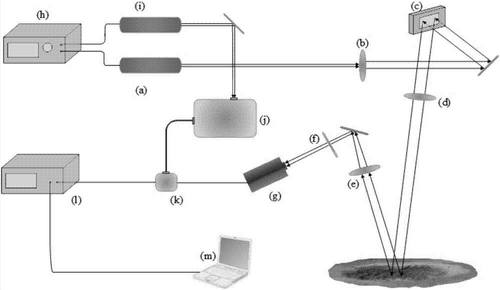
[0020] Such as figure 1 As shown, the large-field crater surface topography imaging system of the present invention uses a single-pixel camera structure combined with a photoelectric avalanche diode and a digital micromirror device to image the crater to obtain the surface topography of the crater, including a synchronous control system, a structured light projection system, Photoelectric detection system, photoelectric gating system and signal processing system. The synchronous control system consists of a synchronous signal generator h, which outputs synchronous signals to the long-pulse laser source a and the short-pulse laser source i. The structured light projection system includes a long pulse laser source a, a beam expander b, a digital micromirror device c (digital micromirror device, DMD) and a projection lens d. The long-pulse laser light source emits pulsed laser after receiving the synchronization signal, and the pulsed laser illuminates the DMD after passing thro...


PUM


Abstract

The invention discloses a large-field-of-view shell crater surface morphology imaging system and a method thereof. The system comprises a synchronous control system, a structural light projection system, a photoelectric detecting system, a photoelectric gated system and a signal processing system. A digital micro-mirror device array projection template which is modulated by a Hadamard matrix is used for sampling. Form an initial resolution image, detail information of a target scene from low resolution to high resolution is gradually acquired, and the detail information is used for reconstructing a final resolution three-dimensional image. The large-field-of-view shell crater surface morphology imaging system and the method thereof have advantages of realizing self-adaptability for the target scene, effectively reducing the number of sampling times, shortening imaging time, realizing high suitability for quick high-resolution three-dimensional imaging application; reducing calculationexpenditure and reducing time required for reconstruction.

Description

technical field [0001] The invention belongs to the technical field of laser three-dimensional imaging, in particular to a surface topography imaging system and an imaging method of a large field of view crater. Background technique [0002] At present, the traditional three-dimensional imaging system mainly adopts fringe projection method and point scanning method ([1] Multi-resolution three-dimensional digital imaging method based on spatially orthogonal fringe projection, CN200410019972.1. [2] A three-dimensional scanning system based on TOF camera and scanning method, CN201510868410.2.). Among them, the three-dimensional measurement process of the fringe projection method can be divided into three steps: first, the fringe projection, the computer generates a standard sinusoidal fringe pattern and is projected onto the surface of the object by the projector, and the fringe structured light is modulated by the object surface and collected by the camera to obtain the deform...

Claims


Application Information

Patent Timeline
Patent Type & Authority Applications(China)
IPC IPC(8): G01B11/24
CPCG01B11/2433
Inventor 邱艳宇王明洋李海波邓国强李杰宋春明程怡豪李干赵章泳张中威
Owner ARMY ENG UNIV OF PLA
Why Eureka
Try Eureka