Combination formed connecting grouting sleeve and manufacturing method thereof

A technology for connecting sleeves and grouting sleeves, which is applied to structural elements, building components, building reinforcements, etc., can solve the problems of low production efficiency, high processing difficulty, difficult quality, etc., and achieves low production cost, simple production process, short cycle effect

Inactive Publication Date: 2018-05-11
LIUZHOU OVM MASCH CO LTD
View PDF5 Cites 2 Cited by
  • Summary
  • Abstract
  • Description
  • Claims
  • Application Information

AI Technical Summary

Problems solved by technology

[0003] The purpose of the present invention is to propose a simple and feasible solution for the problems of low production efficiency, difficult quality assurance, high processing difficulty and high cost of the current general use of integral casting after forming and direct rolling forming of steel pipes. A combined-molded connecting grouting sleeve is provided. The production process of the combined-molded connecting grouting sleeve is simpler, more environmentally friendly, and can be automated in an assembly line, which can improve the product quality and production efficiency of the connecting grouting sleeve and ensure the safety of the structure; at the same time , the present invention also provides the manufacturing method of this combined molding connection grouting sleeve, this method proceeds from the reality of production and installation, the process is simple, and can be implemented, so as to effectively solve the above-mentioned problems existing in the prior art

Method used


Image

  • Combination formed connecting grouting sleeve and manufacturing method thereof
  • Combination formed connecting grouting sleeve and manufacturing method thereof
  • Combination formed connecting grouting sleeve and manufacturing method thereof

Examples


Embodiment 1

[0048] A combined molding connection grouting sleeve

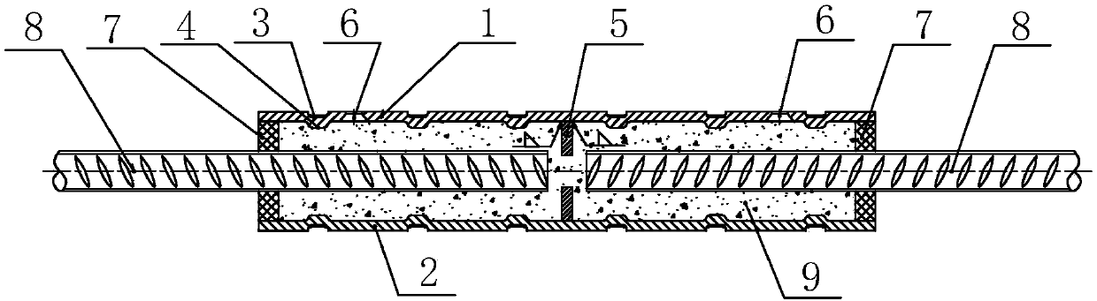
[0049] Such as figure 1 As shown, the combined molding connecting grouting sleeve includes connecting sleeve assembly I1, connecting sleeve assembly II2, two positioning plates 5 and two sealing rings 7 of separate structure; the connecting sleeve assembly I1, connecting sleeve Barrel assembly II2 is formed by stamping steel plate;

[0050] In the state of use, the two connecting sleeve assemblies I1 and II2 are fixedly connected by welding to form an integral tubular connecting sleeve, the positioning block 5 is located in the middle of the tubular connecting sleeve, and the sealing plates 7 are respectively located two ends of the tubular connection sleeve;

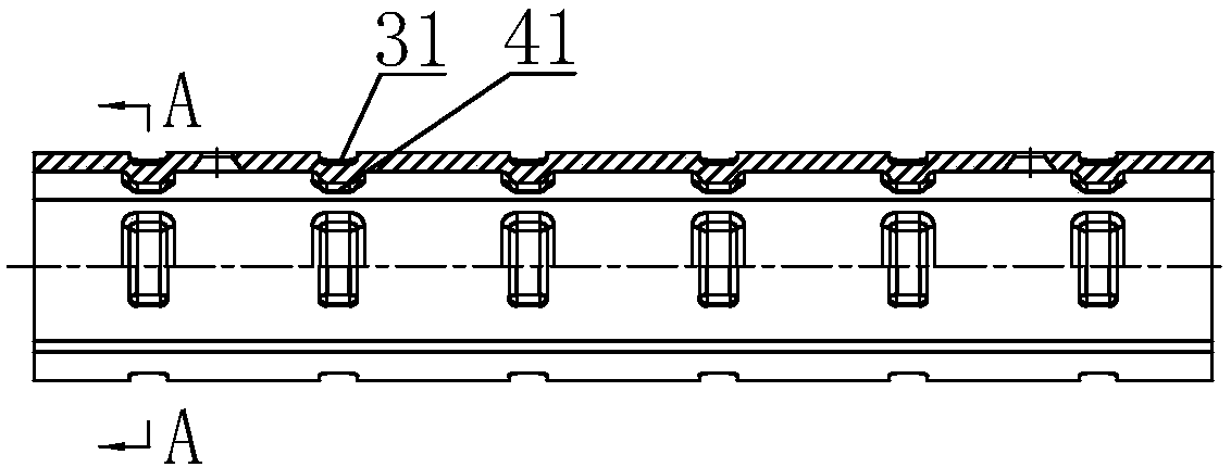
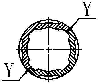
[0051] In order to ensure the bonding strength between the grouting material and the connecting sleeve and improve its pull-out resistance, there are ribs 41, bosses 42 or convex circles 43 on the inner surfaces of the connecting sleeve assembly I1 and connecting ...

Embodiment 2

[0057] A steel bar butt slurry anchor connection joint,

[0058] Such as figure 1 As shown, the steel bar butt grout anchor connection joint includes a connection grouting sleeve, a connected rib 8 and a grouting material 9, and the connection grouting sleeve is a combined connection grouting sleeve described in Embodiment 1. The combined molding connection grouting sleeve includes the connection sleeve assembly I1, the connection sleeve assembly II2, the positioning plate 5 and the sealing ring 7 of the separation structure; There are ribs 41, bosses 42 or convex circles 43 formed by stamping on the surface;

[0059] In the state of use, the two connecting sleeve components I1 and II2 are fixedly connected by welding to form an integral tubular connecting sleeve, and the positioning block 5 is located in the middle of the tubular connecting sleeve, and is separated from The two ends of the tubular connecting sleeve are inserted, and the sealing plates 7 are respectively loc...

Embodiment 3

[0063] A manufacturing method of a combined molding connecting grouting sleeve, that is, the manufacturing method of a combined molding connecting grouting sleeve described in Embodiment 1, which is to separately manufacture the connecting sleeve assembly I1, the connecting sleeve assembly II2 and the positioning block 5, and then, It is composed of a tubular connection sleeve that is fixedly connected into a whole by welding, including the following steps:

[0064] A. Material preparation, selected process and selected equipment:

[0065] A1. According to the diameter of the connected rib 8 and the size of the designed connecting sleeve, it is determined that the connecting sleeve is stamped and formed by two parts and then assembled and welded, and the stamping forming process is formulated;

[0066] A2. According to the selected stamping forming process, carry out mold making and select appropriate stamping equipment;

[0067] B. Blanking: Punching or cutting the steel pla...


PUM


Abstract

A combination formed connecting grouting sleeve comprises two to eight connecting sleeve assemblies which are each of a separating structure, positioning plates and sealing rings. Under the using state, the two to eight connecting sleeve assemblies are fixedly connected into an overall tubular connecting sleeve in a welding or bolt connecting mode, the positioning plates are located in the middlesof the tubular connecting sleeve, and the sealing rings are correspondingly located at the two ends of the tubular connecting sleeve; the inner surface of each connecting sleeve assembly of the separating structure is provided with a protruding rib, a boss or a protruding circle and a groove or a pit, wherein the protruding rib, the boss or the protruding circle and the groove or the pit are formed by punching, and the groove or the pit are corresponding to the outer surface; and the middles of all the connecting sleeve assemblies are provided with the positioning plates fixedly connected ina welded mode. According to the combination formed connecting grouting sleeve, the production technology is simple, convenient and environmentally friendly, automated production of an assembly line can be achieved, the production cost is low, the product quality and the production efficiency of the connecting grouting sleeve can be improved, and structural safety of a steel bar butting grouting anchor connecting joint is ensured.

Description

technical field [0001] The invention relates to a connecting grouting sleeve and a manufacturing method thereof, in particular to a combined molding connecting grouting sleeve and a manufacturing method thereof. Background technique [0002] With the development of prefabricated concrete structures in China, the connection methods and connection products of the main stressed steel bars between the prefabricated components are various, and the technology is becoming more and more mature. The ends of the two connected steel bars are inserted into the connecting grouting sleeve, and the gap is filled with grouting material. Since the outer surface of the steel bar and the inner surface of the sleeve each have distributed transverse ribs, the grouting material is composed of high-performance cement mortar or epoxy mortar After solidification, the three are embedded and occluded to realize the connection. There are two ways of making grouting sleeves in the market: machining aft...

Claims


Application Information

Patent Timeline
Patent Type & Authority Applications(China)
IPC IPC(8): E04C5/16
CPCE04C5/165
Inventor 谢正元蒋业东苏强
Owner LIUZHOU OVM MASCH CO LTD
Why Eureka
Try Eureka