Solar vacuum tube, solar heat collector and application method of solar vacuum tube
A solar collector and vacuum tube technology, applied in the field of solar vacuum tubes and solar thermal collectors, can solve the problems of low thermal efficiency of solar vacuum tubes, inability to replace wearing parts, and high cost of use, and achieves improved heat collection efficiency, easy replacement, and thermal conductivity. Good results
- Summary
- Abstract
- Description
- Claims
- Application Information
AI Technical Summary
Problems solved by technology
Method used
Image
Examples
Embodiment 1
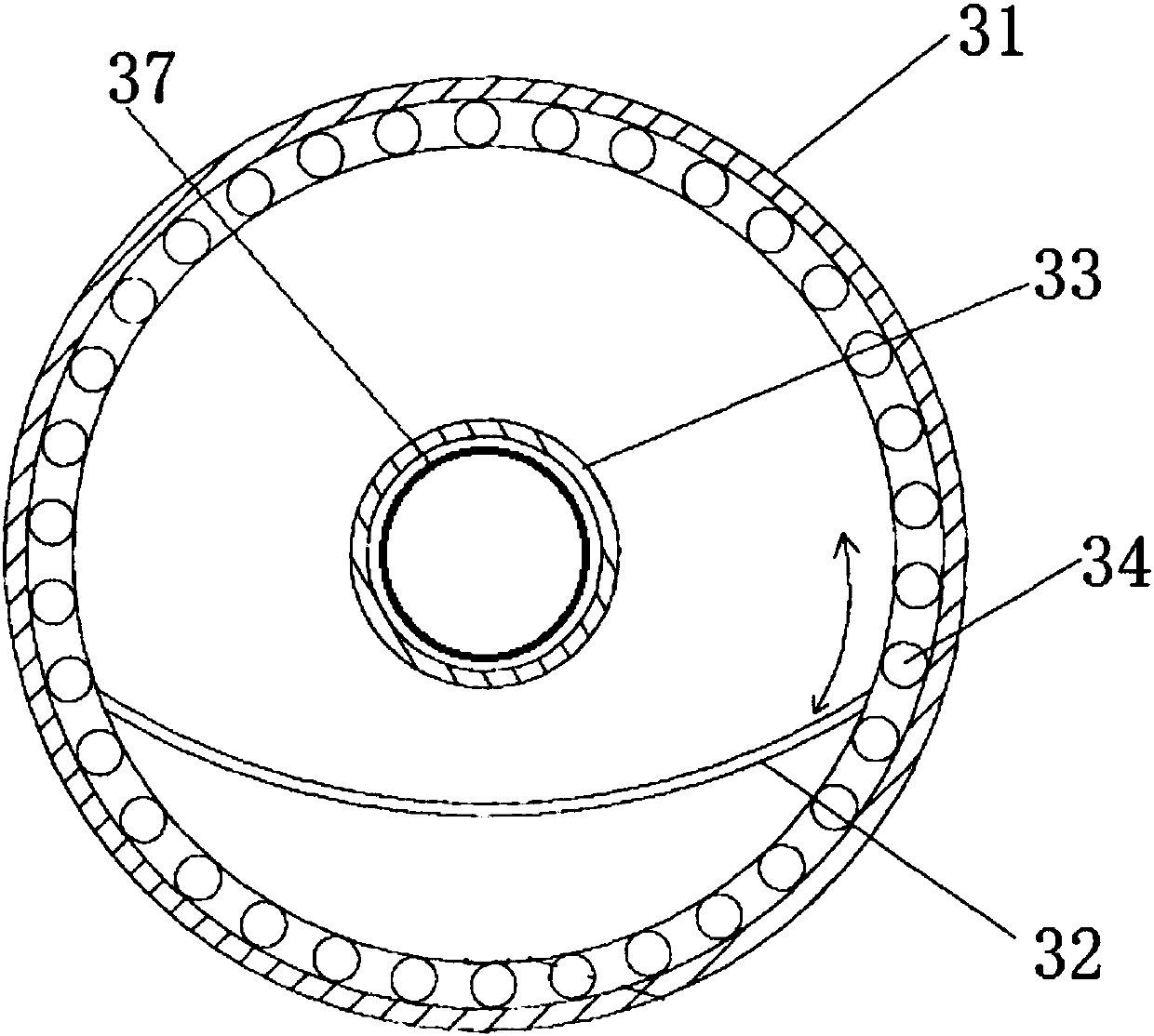
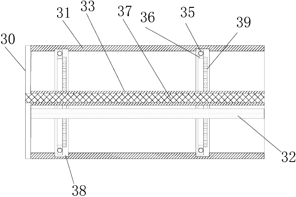
[0018] Example 1 as Figure 1 to Figure 2 As shown, the solar vacuum tube of the present embodiment comprises a transparent outer tube 31 with an open end and a transparent inner tube 33, a C-shaped reflector 32, a heat pipe 37, an end cover 30, two magnetic couplings 34, and the opening of the transparent outer tube 31 The end is sealed with the end cap 30, and the center of the end cap 30 is provided with a through hole. The closed end of the transparent inner tube 33 passes through the through hole in the center of the end cap 30 and is fixedly arranged in the transparent outer tube 31 along the axial direction of the transparent outer tube 31. Place the open end of the transparent inner tube 33 on the end cover 30, and after the heat pipe 37 and the transparent inner tube 33 are inserted and matched, the through hole and the heat pipe 37 are sealed, and the heat transfer medium to be heated circulates in the heat pipe 37; C The shape reflector 32 is rotatably arranged in t...
Embodiment 2
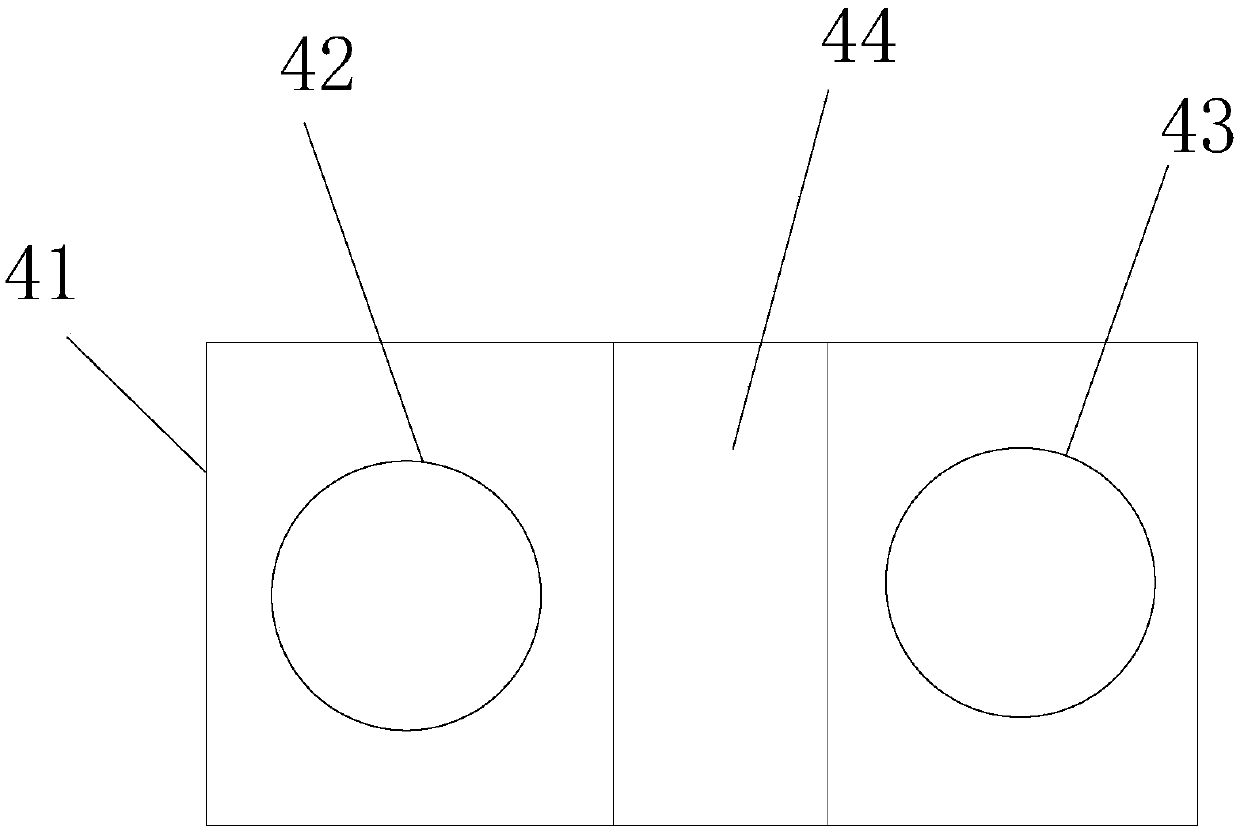
[0020] A kind of solar thermal collector, comprises above-mentioned solar vacuum tube, also comprises the tracking driving device that is used to drive the prime mover permanent magnet to rotate, as image 3 The tracking driving device shown includes a rotating base 41, a rotating motor, a first photodiode 42, a second photodiode 43, and a light shield 44. The rotating motor (not shown in the figure) is in transmission cooperation with the rotating base 41, and the prime mover The permanent magnet and the rotating base 41 are driven and matched so that the rotating motor can drive the rotating base 41 to rotate synchronously with the prime mover permanent magnet. The first photodiode 42 and the second photodiode 43 are arranged on both sides of the upper end surface of the rotating base 41. The light shield 44 is placed between the first photodiode 42 and the second photodiode 43; the tracking drive device also includes a control circuit ( not shown in the figure), the control...
Embodiment 3
[0022]The specific usage method of the solar heat collector described in Embodiment 2 is as follows: the upper end surface of the rotating base 41 and the reflector 32 are both set towards the sun, and the axial centerline of the reflector 32 is consistent with or parallel to the extending direction of the shading plate 44 Setting, during the initial state, the first photodiode 42 and the second photodiode 43 of the same model on the upper end surface of the base 41 are turned towards the sun; The current signals generated by the photodiode 42 and the second photodiode 43 are sent to the control circuit, and the control circuit compares the magnitude of the current generated by the first photodiode 42 and the second photodiode 43. When the currents generated by the two are the same, it indicates that the first Photosensitive diode 42, the second photosensitive diode 43 are all facing the sun, and now reflective plate 32 is placed on the angle of facing the sun equally, needn't ...
PUM
 Abstract
Description
Claims
Application Information
 - R&D
- Intellectual Property
- Life Sciences
- Materials
- Tech Scout
- Unparalleled Data Quality
- Higher Quality Content
- 60% Fewer Hallucinations
Browse by: Latest US Patents, China's latest patents, Technical Efficacy Thesaurus, Application Domain, Technology Topic, Popular Technical Reports.
© 2025 PatSnap. All rights reserved.Legal|Privacy policy|Modern Slavery Act Transparency Statement|Sitemap|About US| Contact US: help@patsnap.com


