
Spectrometer or imaging spectrometer

An imaging spectrometer and spectrometer technology, applied in the field of spectrometer or imaging spectrometer, can solve the problems affecting the acquisition flexibility of the spectrometer, and achieve the effect of convenient adjustment and stable structure

Pending Publication Date: 2018-05-11
DALIAN INST OF CHEM PHYSICS CHINESE ACAD OF SCI
View PDF6 Cites 8 Cited by
  • Summary
  • Abstract
  • Description
  • Claims
  • Application Information

AI Technical Summary

Problems solved by technology

The grating of the transmission grating spectrometer is usually fixed, which affects the acquisition flexibility of the spectrometer

Method used


Image

  • Spectrometer or imaging spectrometer
  • Spectrometer or imaging spectrometer
  • Spectrometer or imaging spectrometer

Examples


Embodiment 1

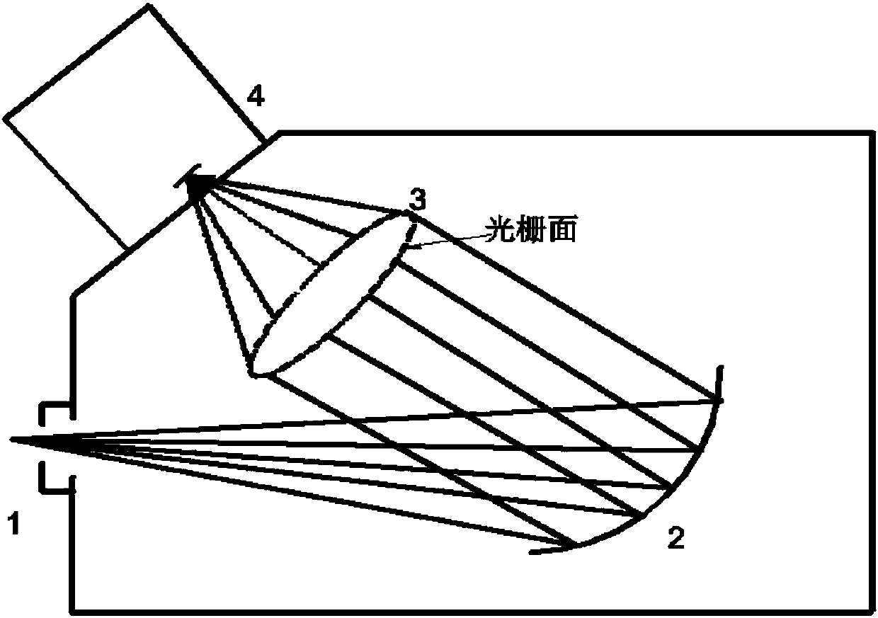
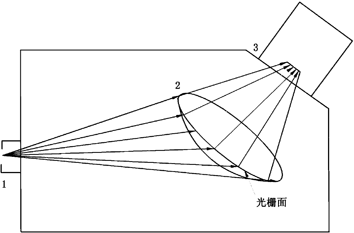
[0063] figure 1 and 2 Shown is the optical path diagram of a spectrometer or imaging spectrometer including a focusing lens grating 3, where the focusing lens grating 3 can be selected Figure 4 For the focusing lens gratings shown in 4-1, 4-2, 4-3, 4-4 and 4-5, the incident slit 1 is on a focal plane of the collimating reflective concave mirror 2, and incident from the incident slit 1 The signal light becomes parallel light after being collimated and reflected by the concave mirror 2, and then split and focused by the focusing lens grating 3.

Embodiment 2

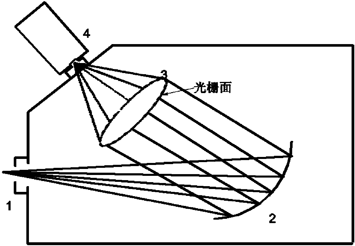
[0065] image 3 Shown is the optical path diagram of a spectrometer or imaging spectrometer comprising a collimating and focusing lens grating 2, wherein the collimating and focusing lens grating 2 can be selected from Figure 4 In one of 4-6 and 4-7, the signal light passes through the incident slit 1, is collimated and focused on the lens grating 2, and is correspondingly imaged on the multi-channel imaging detector CCD.

Embodiment 3

[0067] Figure 6 A Raman spectrometer is provided, including an entrance slit 1, a filter 5, a collimating reflective concave mirror 2, a focusing lens grating 3, and a detector 4. The excitation light is a 532nm laser, and the Raman scattering signal generated after incident on the sample enters the Raman spectrometer, and the 532nm filter can be placed in front of the slit (such as Figure 6-2 shown) or after the slit (such as Figure 6-1 shown). After the Raman signal is filtered out by the filter, the Rayleigh line is incident on the reflective concave lens 2, and becomes parallel light (the optical path is as follows: Figure 5-1 , 5-2). Parallel light is incident on the surface of the focusing lens grating 3, that is, the grating facet, the grating parameter is 1200 / mm, and the focusing lens grating is as follows Pic 4-1 , 4-2, 4-3, 4-4. The scattered light is split according to the grating equation (Bragg equation) and then focused by the rear lens, and the signal ...


PUM


Abstract

The present invention provides a spectrometer or an imaging spectrometer, and in particular relates to a spectrometer or an imaging spectrometer capable of integrating a transmission grating and a focusing lens or integrating a collimation element, the transmission grating, and the focusing lens. The spectrometer or the imaging spectrometer includes an entrance slit, a detector, the collimation element, a focusing transmission grating or a collimating focusing lens grating. The spectrometer includes the focusing lens grating. The focusing lens grating is engraved with a grating fringe on the side close to the focusing lens. The lens grating can realize the functions of splitting and focusing, or simultaneously realize the functions of collimating, splitting and focusing; the focusing lensgrating is an achromatic focusing lens grating. Since the grating and the focusing lens are integrated, the problem that the conventional transmission grating cannot rotate can be solved. The advantages that a reflective grating can be rotated, the transmission grating in high and uniform in transmittance, and the reflective grating and the transmission grating are same in response to polarized light are combined to complete spectral splitting and focusing output.

Description

technical field [0001] The invention relates to a spectrometer or an imaging spectrometer which integrates a transmission grating and a focusing lens or integrates a collimation element, a transmission grating and a focusing lens. Background technique [0002] Spectrometers or imaging spectrometers are widely used in spectral detection of samples, such as spectrophotometer detection, absorption spectrum detection, fluorescence spectrum detection, Raman spectrum detection, etc. Spectroscopic techniques allow rapid and accurate analysis of samples. Spectroscopy is widely used in food, security, physical evidence, minerals, environment, chemistry, materials, biology, ocean and many other fields. Sample types include solid, powder, liquid, gas, interface, colloid and other forms. At present, spectrometers are widely used in various fields, and their applications are becoming more and more extensive. [0003] The principle of the spectrometer is: the light of the sample is foc...

Claims


Application Information

Patent Timeline
Patent Type & Authority Applications(China)
IPC IPC(8): G01N21/31G01N21/33G01N21/65
CPCG01N21/31G01N21/33G01N21/65
Inventor 李灿冯兆池张莹王鹏唐宇轩
Owner DALIAN INST OF CHEM PHYSICS CHINESE ACAD OF SCI
Learn More