High-strength and high-ductility concrete fabricated frame structure system and connecting system thereof

A technology of high ductility concrete and frame structure, applied in the direction of truss structure, building structure, construction, etc., can solve the problems of difficult to determine the state of the sleeve, hidden dangers, affecting the construction period, etc., to improve the integrity and seismic performance, high Tensile strain hardening, solving the effect of bar crowding

Pending Publication Date: 2018-05-15
XI'AN UNIVERSITY OF ARCHITECTURE AND TECHNOLOGY
View PDF7 Cites 7 Cited by
  • Summary
  • Abstract
  • Description
  • Claims
  • Application Information

AI Technical Summary

Problems solved by technology

[0004] At present, my country's prefabricated frame structure mainly uses sleeve grouting to connect steel bars, and then pours ordinary concrete in the core area of ​​the joints. There are mainly the following problems: (1) Due to the large volume, heavy weight and complex connection structure of prefabricated components, In addition, the labor force level in China's construction industry is low, which increases the difficulty of prefabricated building construction that requires a high degree of refinement; (2) Both the sleeve grouting connection and the restraint paddle-anchor conn

Method used


Image

  • High-strength and high-ductility concrete fabricated frame structure system and connecting system thereof
  • High-strength and high-ductility concrete fabricated frame structure system and connecting system thereof
  • High-strength and high-ductility concrete fabricated frame structure system and connecting system thereof

Examples


Embodiment 1

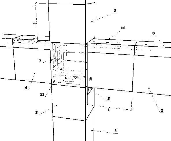
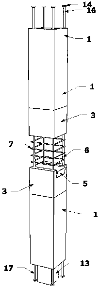
[0036] This embodiment provides a figure 1 The high-strength and high-ductility concrete fabricated frame structure system shown includes a prefabricated reinforced concrete column 1, a prefabricated reinforced concrete beam 2, and the joint core area is formed at the connection between the prefabricated reinforced concrete column 1 and the prefabricated reinforced concrete beams 2 on both sides. The prefabricated reinforced concrete column 1 includes a concrete prefabricated column, a column longitudinal bar 6 and a column stirrup 7, and the column longitudinal bar 6 runs through the upper and lower ends of the concrete precast column to form an upper reserved column longitudinal bar 16 and a lower reserved column longitudinal bar 17 respectively. In addition, the core area of ​​the node is exposed, and column stirrups 7 are reserved outside the column longitudinal reinforcement 6 of the exposed part. The top of the prefabricated reinforced concrete column 1 in the core area o...

Embodiment 2

[0041] On the basis of Embodiment 1, this embodiment provides a high-strength and high-ductility concrete assembled frame structure system. The prefabricated reinforced concrete column 1 is provided with a prefabricated core column 13 in the middle of the lower end, and the prefabricated core column 13 is used for assembly. When supporting the prefabricated reinforced concrete column 1, the longitudinal reinforcement 16 of the upper reserved column and the longitudinal reinforcement 17 of the lower reserved column are all fixedly provided with an anchor plate 14 at the end of the longitudinal reinforcement;

[0042] The upper prefabricated reinforced concrete column 1 and the lower prefabricated reinforced concrete column 1 are staggered and overlapped through the corresponding longitudinal reinforcement 17 of the lower reserved column and longitudinal reinforcement 16 of the upper reserved column. Lap the outside of the lap joint with reserved stirrups. Prefabricated reinforced...

Embodiment 3

[0051] On the basis of Embodiment 1, this embodiment provides a high-strength and high-ductility concrete assembly frame structure system, and the parts of the prefabricated reinforced concrete columns 1 and prefabricated reinforced concrete beams 2 near the node core area are respectively high-strength and high-ductility concrete Prefabricated column ends 3 and high-strength and high-ductility concrete prefabricated beam ends 4, the height H of the high-strength and high-ductility concrete precast column ends 3 is 0 to 2 times the column width, and the length L of the high-strength and high-ductility concrete precast beam ends 4 is 0-2 times 2 times the beam height.

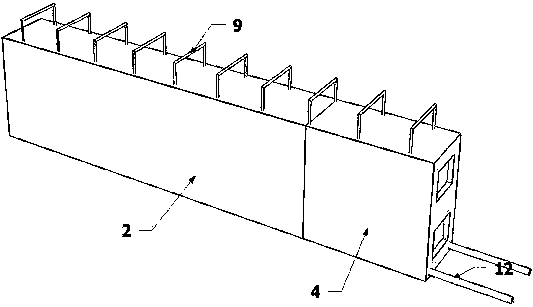
[0052] Such as Figure 4 As shown, the high-strength and high-ductility concrete prefabricated beam end 4 of the prefabricated reinforced concrete beam 2 is prefabricated by high-strength and high-ductility concrete, and the rest is ordinary concrete. The post-cast high-strength high-ductility concrete layer 11...


PUM

PropertyMeasurementUnit
Lengthaaaaaaaaaa
Specific surface areaaaaaaaaaaa
Particle sizeaaaaaaaaaa

Abstract

The invention provides a high-strength and high-ductility concrete fabricated frame structure system and a connecting system thereof. According to the high-strength and high-ductility concrete fabricated frame structure system, a column longitudinal bar penetrates through the upper end and the lower end of a concrete prefabricated column to form an upper prefabricated column longitudinal bar and alower prefabricated column longitudinal bar and is exposed in a joint core area, column stirrups are prefabricated outside the exposed parts of the column longitudinal bar, and a prefabricated corbelis arranged at the top of a prefabricated reinforced concrete column in the joint core area; the lower portions of two side prefabricated reinforced concrete beams are in lap connection in the jointcore area through a lower longitudinal bar, the upper portions of the two side prefabricated reinforced concrete beams are connected through a beam upper longitudinal bar, which penetrates through beam stirrups and the joint core area and are then poured with high-strength and high-ductility concrete. According to the high-strength and high-ductility concrete fabricated frame structure system, thejoint column longitudinal bar and the beam upper longitudinal bar have no break in the joint core area, so that steel bar connection can be avoided in the joint core area with complex stress but at column inflection points with small bending moment, and structural integrity and anti-seismic properties can be avoided. Without sleeves, the high-strength and high-ductility concrete fabricated framestructure system is convenient to manufacture and install, reduces working procedures, professionals and achieves easy control.

Description

technical field [0001] The invention belongs to the technical field of prefabricated concrete structures, and in particular relates to a high-strength and high-ductility concrete prefabricated frame structure system and a connection method. Background technique [0002] Frame structure is one of the most commonly used structural forms in precast concrete structures. Because its components are lighter than box structures, prefabricated slab structures or prefabricated shear wall structures, prefabricated concrete frame structures have more advantages in the transportation of components. And the prefabricated frame structure is one of the high-rise frame structure systems, and there have been engineering applications of prefabricated concrete frame structures in high-rise buildings abroad. [0003] Since the prefabricated components are prefabricated in the factory, the quality of the prefabricated components can be well guaranteed, and the safety of the prefabricated structu...

Claims


Application Information

Patent Timeline
IPC IPC(8): E04B1/20E04B1/21E04C3/20E04C3/44E04G21/00C04B28/04
CPCE04B1/20E04B1/21E04C3/20E04C3/44E04G21/00C04B28/04C04B18/08C04B18/146C04B14/06C04B14/48C04B16/0641
Inventor 邓明科马福栋叶旺
Owner XI'AN UNIVERSITY OF ARCHITECTURE AND TECHNOLOGY
Why Eureka
Try Eureka