Synchronous motion roundness error separation device and method

A roundness error and error separation technology, which is applied in the field of precision instrument manufacturing and measurement, can solve the problems of model principle error, spindle radial rotation error separation error separation of ultra-precision roundness measuring instruments, turntable radial rotation error, and complicated calculation. , to achieve the effect of few calculation steps, fast detection speed and simple calculation

Active Publication Date: 2018-05-15
浙理氢能(杭州)科技有限公司
View PDF13 Cites 5 Cited by
  • Summary
  • Abstract
  • Description
  • Claims
  • Application Information

AI Technical Summary

Problems solved by technology

But the disadvantages are also obvious. For example, the increase in the number of sensors will lead to inconsistent characteristics of each sensor, the layout of the sensors is not on the same measurement section, and there are problems such as zero points in the transfer function.
[0008] The problems in the above method are: 1. The signal is transformed into the frequency domain by Fourier transform for error separation, and the spectrum information of the separated signal is obtained, and then the inverse Fourier transform is performed to finally obtain the separated signal. The calculation is complicated and has Truncation and rounding errors; 2. Due to the use of Fourier transform, there is a problem of harmonic suppression in the separated signal, and there is a principle error in the model. The corresponding improvement method can only solve the problem of no harmonic suppression in a certain range, and cannot achieve full There is no harmonic suppression in the band; 3. The roundness error of the measured piece, the radial rotation error of the spindle of the ultra-precision roundness measuring instrument and the radial rotation error of the error separation turntable cannot be separated at the same time

Method used


Image

  • Synchronous motion roundness error separation device and method
  • Synchronous motion roundness error separation device and method
  • Synchronous motion roundness error separation device and method

Examples


specific Embodiment approach 1

[0045] The following embodiments are embodiments of the present invention based on a synchronous movement type circularity error separation device.

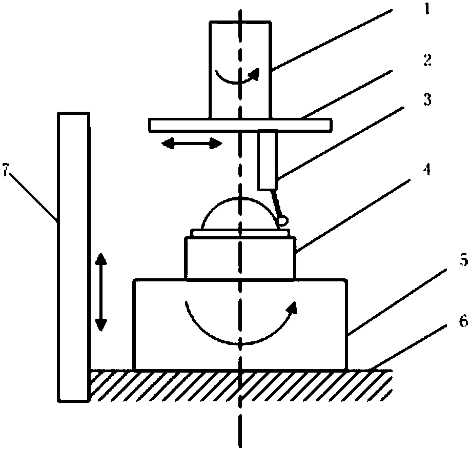
[0046] The roundness error separation device based on synchronous motion in this embodiment is characterized in that it includes a rotary main shaft 1, a lateral guide rail 2, a displacement sensor 3, an error separation turntable 5, a worktable 6 and a vertical guide rail 7, and the rotary main shaft 1 and the lateral The guide rail 2 is connected through the center, the displacement sensor 3 moves horizontally on the transverse guide rail 2, the rotary spindle 1, the transverse guide rail 2 and the displacement sensor 3 move coaxially, the error separation turntable 5 is placed on the workbench 6, and the error separation turntable 5 and The tested piece 4 rotates together, and the workbench 6 drives the error separation turntable 5 to move up and down along the vertical guide rail 7 with the tested piece 4 to find the position ...

specific Embodiment approach 2

[0049] The following embodiments are embodiments of the method for separating roundness errors based on synchronous motion in the present invention.

[0050] The present invention is based on the synchronous movement type circularity error separation method, comprises the following steps:

[0051] Step a, place the error separation turntable 5 on the workbench 6, and roughly adjust the error separation turntable 5 to be concentric with the rotary spindle 1;

[0052] Step b, determine the section to be measured of the tested piece 4, lift the workbench 6 along the vertical guide rail 7, make the section to be tested of the tested piece 4 and the measuring head of the displacement sensor 3 be on the same section, adjust the tested piece 4, so that The section to be measured of the tested part 4 is concentric with the error separation turntable 5;

[0053] Step c. The error separation turntable 5 and the measured piece 4 are regarded as a whole, and the error separation turntabl...


PUM


Abstract

The invention provides a synchronous motion roundness error separation device and method, which belongs to the technical field of precision instrument manufacturing and measurement. According to the method, an error separation turntable which can follow to rotate in the same direction as the rotation spindle of an ultra-precision roundness error measuring instrument is introduced in the ultra-precision roundness measuring instrument; and through three measurements of a circumferential signal containing different system components, any one of the roundness error of a tested part, the radial rotation error of the spindle of the ultra-precision roundness measuring instrument and the radial rotation error of the error separation turntable is separated. Compared with the most widely used multi-step method, the method solves a problem completely in the airspace, does not involve the Fourier transform, completely avoids harmonic suppression, has the advantage of simple measurement and calculation process, prevents model errors, and provides a new idea for ultra-precision roundness error separation.

Description

technical field [0001] The invention is based on a synchronous movement type roundness error separation device and method, belonging to the technical field of precision instrument manufacturing and measurement. Background technique [0002] In recent years, the continuous development of the field of ultra-precision machining has directly led to the lack of corresponding testing equipment for the processing accuracy of many processing equipment, so that the processing accuracy cannot be further improved. Taking roundness as an example, the roundness error of modern astronomical telescopes has reached ±5nm, the roundness of gyroscopes on spaceships is required to be less than 10nm, and the roundness error of any cross-section of silicon crystal balls with high-precision density references has reached within 10nm. The radial rotation error of the instrument spindle of the highest-precision roundness measuring instrument is also about ±10nm, which makes it impossible to measure ...

Claims


Application Information

Patent Timeline
Patent Type & Authority Applications(China)
IPC IPC(8): G01B21/00
CPCG01B21/20
Inventor 不公告发明人
Owner 浙理氢能(杭州)科技有限公司
Why Eureka
Try Eureka