Forming equipment for producing concrete components

A forming equipment and concrete technology, which is applied in the field of 2/1u-shaped, full-u-shaped, rectangular and trapezoidal concrete components, can solve the problem of unsatisfactory product strength, frost resistance, impermeability and service life, technical and Higher operating requirements, affecting product quality and work efficiency, etc., to achieve the effects of good frost resistance and anti-seepage performance, compact structure of the whole machine, and good rigidity

Inactive Publication Date: 2018-05-18
嘉兴大桥南方混凝土有限公司
View PDF0 Cites 0 Cited by
  • Summary
  • Abstract
  • Description
  • Claims
  • Application Information

AI Technical Summary

Problems solved by technology

[0002] The existing forming equipment used to produce concrete components required for housing construction, roads, water conservancy projects, etc. requires three hydraulic cylinders for hydraulic mold removal, so the energy consumption loss is large, and the three hydraulic cylinders can be operated synchronously. It requires high technology and operation, so the cost is high, and there are situations where the machine tool fails or even is damaged due to synchronization errors and affects product quality and work efficiency.
In addition, the forming equipment of the prior art has unsatisfactory drainage and exhaust effects in the process of extruding concrete, so that the compactness of the formed product is insufficient, and the product strength, frost resistance, and impermeability and service life are not ideal.

Method used


Image

  • Forming equipment for producing concrete components
  • Forming equipment for producing concrete components

Examples


Embodiment 1

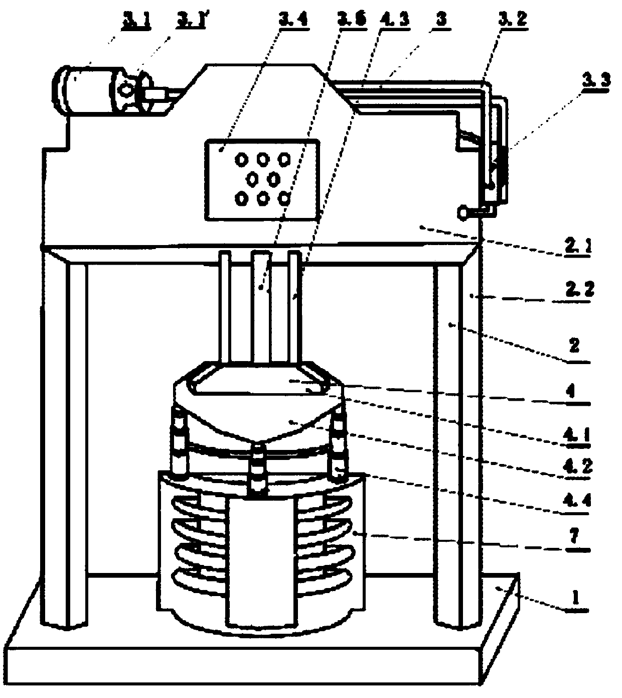
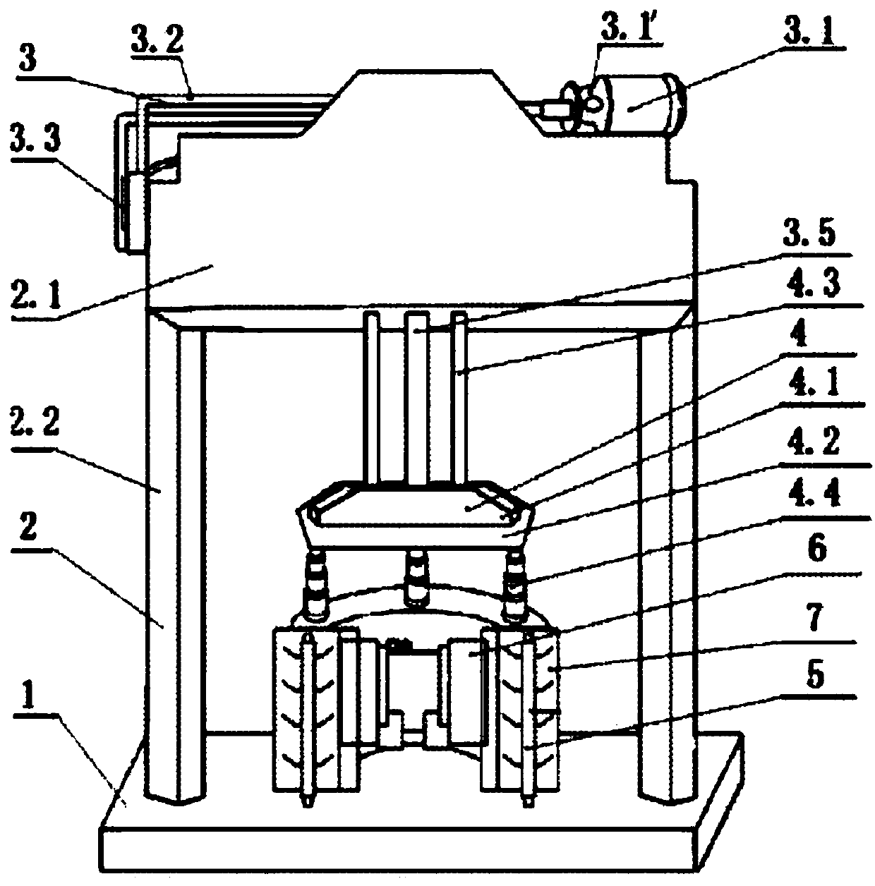
[0020] Such as figure 1 , 2 As shown, a forming equipment for producing concrete components has a machine base 1 and a gantry frame 2 composed of a beam 2.1 and a column 2.2; one includes a hydraulic pump motor 3.1, a hydraulic pump 3.1', a hydraulic oil pipe 3.2, Reversing valve 3.3, electric control box 3.4, and hydraulic system 3 of hydraulic cylinder 3.5; there is also a pressure head system 4 including pressure head seat 4.1, working pressure head 4.2, at least two balance guide rails 4.3, and telescopic rod 4.4 There is only one hydraulic cylinder 3.5, which is vertically installed in the middle of the beam 2.1; the lower end of the hydraulic rod of the hydraulic cylinder 3.5 is fixedly connected to the pressure head seat 4.1; the lower end of the balance guide rail 4.3 is fixedly connected to the pressure head seat 4.1, and the balance guide rail 4.3 The upper part is slidingly matched with the guide member fixed in the beam 2.1. The balance guide rail 4.3 is parallel ...

Embodiment 2

[0022] The difference from the above-mentioned embodiment 1 is that the balance guide rail 4.3 is evenly distributed on the outside of the hydraulic rod of the hydraulic cylinder 3.5, and there are three balance guide rails 4.3; , it can also be suspended on the column 2.2 or the beam 2.1; the concrete mold 7 is rectangular.


PUM


Abstract

The invention relates to forming equipment for producing concrete components. The forming equipment is used for producing the formed concrete components required by house buildings, roads, water conservancy projects and the like, and is especially suitable for producing the full-U-shaped, 2 / 1-of-U-shaped, rectangular and trapezoidal concrete components. The forming equipment comprises a machine seat, a gantry-type rack composed of a crossbeam and a vertical column, a hydraulic system and a pressure head system. Only one hydraulic oil cylinder is vertically mounted in the middle of the crossbeam. The lower end of a hydraulic rod of the hydraulic oil cylinder is fixedly connected with a pressure head seat. The lower end of a balancing guiding rail is fixedly connected with the pressure headseat. A working pressure head is connected to the lower part of the pressure head seat. The upper end of a telescopic rod is connected with the working pressure head. The lower end of the telescopic rod is connected with a concrete die. The forming equipment for producing the concrete components has the advantages that the forming equipment for producing the concrete components can improve motility in the process of concrete forming, drainage and exhaust are advantageously conducted, the product compactness is high, the strength is high, the frost resistance and the anti-seepage performance are good, the whole structure is compact, operation is convenient, the rigidity is good, the life is long, the efficiency is high, and energy consumption is low.

Description

technical field [0001] The invention relates to a forming equipment for producing concrete components, which is used for producing shaped concrete components required for building construction, roads, water conservancy projects, etc., and is especially suitable for producing full U-shaped, 2 / 1u-shaped, rectangular and trapezoidal concrete components. Background technique [0002] The existing forming equipment used to produce concrete components required for housing construction, roads, water conservancy projects, etc. requires three hydraulic cylinders for hydraulic mold removal, so the energy consumption loss is large, and the three hydraulic cylinders can be operated synchronously. Then, the technical and operational requirements are relatively high, so the cost is high, and there are cases where the machine tool fails or even is damaged due to synchronization errors and affects product quality and work efficiency. In addition, the forming equipment of the prior art has u...

Claims


Application Information

Patent Timeline
IPC IPC(8): B28B3/04
CPCB28B3/022B28B3/04
Inventor 陆建华
Owner 嘉兴大桥南方混凝土有限公司
Why Eureka
Try Eureka