Spherical motor rotor position detection method based on MEMS sensor

A technology of rotor position detection and spherical motor, which is applied in the direction of motor generator testing, instrumentation, and electrical measurement, can solve the problems of increasing system complexity, increasing frictional resistance, and inconvenient system operation, achieving low computational complexity and ensuring high Accuracy, effect of simple hardware structure

Inactive Publication Date: 2018-05-22
TIANJIN UNIV
View PDF9 Cites 16 Cited by
  • Summary
  • Abstract
  • Description
  • Claims
  • Application Information

AI Technical Summary

Problems solved by technology

[0003] However, there are few methods for detecting the rotor position of spherical motors based on MEMS (Micro Electron Mechanical Systems), that is, microelectromechanical systems.
The measurement method based on the sliding rail bracket and the rotary encoder requires a special lead structure to couple the rotor direction and the e

Method used


Image

  • Spherical motor rotor position detection method based on MEMS sensor
  • Spherical motor rotor position detection method based on MEMS sensor
  • Spherical motor rotor position detection method based on MEMS sensor

Examples


Embodiment Construction

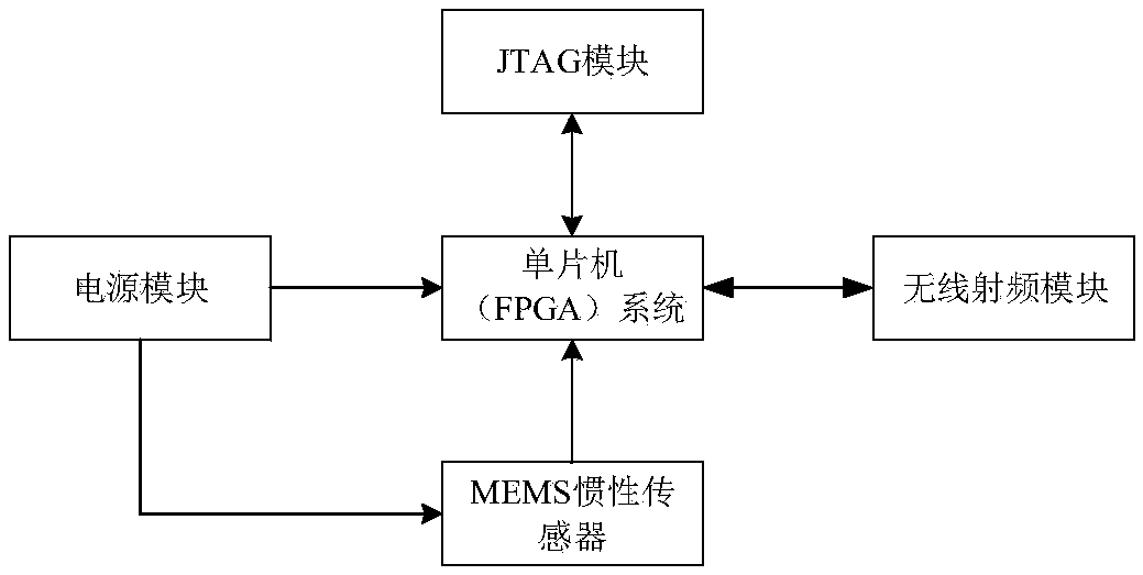
[0039] The invention provides a design method of a MEMS device-based spherical motor rotor position detection system, and its accuracy is verified through a test platform. The invention will be described in detail below in conjunction with the accompanying drawings and examples.

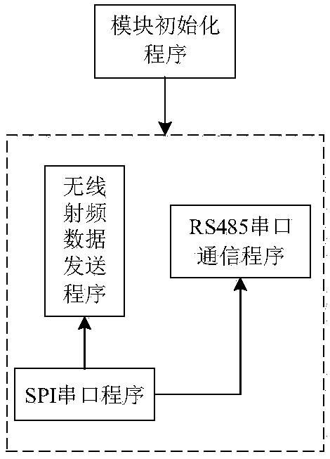
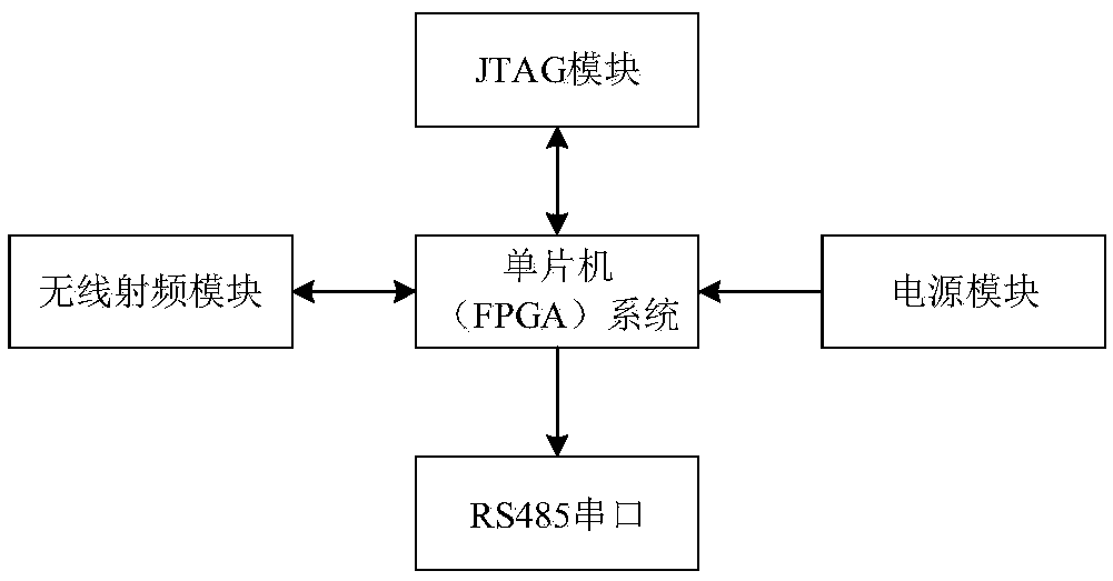
[0040] Design the data acquisition and processing module of the spherical motor rotor position detection system, such as figure 1 , figure 2 shown. It includes a single-chip microcomputer or FPGA responsible for control and filtering processing, MEMS devices (take MPU9250 as an example) and a radio frequency transceiver module. In order to make data processing easier, the center of the MPU9250 chip coincides with the spherical center of the spherical motor rotor. Write programs, MCU or FPGA using I 2 The C bus or SPI bus communicates with the MPU9250, and regularly reads the three-axis angular velocity, three-axis acceleration and three-axis magnetic field strength in the MPU9250.

[0041]The sph...


PUM


Abstract

The invention relates to a spherical motor rotor position detection method based on an MEMS (Micro Electron Mechanical Systems) sensor. The method comprises steps: the original data of the MEMS sensorare acquired; zero bias error compensation is carried out on an angular velocity, and ellipsoid fitting compensation is carried out on an acceleration and a magnetic induction intensity; the angularvelocity, the acceleration and the magnetic induction intensity data after compensation are subjected to complementary filter-based data fusion and are substituted to a quaternion differential equation to obtain an attitude updating quaternion; the attitude updating quaternion is converted to an Euler angle, the change characteristics of the Euler angle in different intervals are combined, accurate interval transfer judgment is made, and conversion of the Euler angle in a full angle range change condition can be realized.

Description

technical field [0001] The invention belongs to the technical field of spherical motor control, and in particular relates to a method for detecting the rotor position of a spherical motor. Background technique [0002] With the continuous development of modern industrial technology, precision devices such as robots and manipulators that perform complex movements have been widely used. Such devices often need to complete multi-dimensional motion control in space. However, from a kinematic point of view, the spherical structure of the rotor is most conducive to multi-dimensional motion. It can be positioned and work in any direction in space, but its structural analysis is more difficult. As an indispensable feedback control link of the motor, the position detection of the spherical motor rotor is one of the key technologies in the motor control system, and its resolution directly affects the control accuracy of the system, so the rotor position detection technology is urgent ...

Claims


Application Information

Patent Timeline
IPC IPC(8): G01R31/34
CPCG01R31/346
Inventor 李桂丹冯家煦李斌
Owner TIANJIN UNIV
Why Eureka
Try Eureka