Welding device capable of achieving rotational feeding

A welding device and rotary feeding technology, which is applied in the direction of auxiliary devices, welding equipment, auxiliary welding equipment, etc., can solve the problems of time-consuming and laborious, and achieve the effects of improved welding efficiency, low processing cost, and simple structure

Inactive Publication Date: 2018-05-25
TIANJIN HAOHANG COMPOSITE PIPE
View PDF0 Cites 1 Cited by
  • Summary
  • Abstract
  • Description
  • Claims
  • Application Information

AI Technical Summary

Problems solved by technology

[0002] When the existing welding equipment is performing welding operations, it is necessary to fix the parts to be welded on the fixture first, and then perform welding after the material is loaded. , a rotary feeding welding device that can solve this problem and realize continuous and uninterrupted operation still needs further research and development

Method used


Image

  • Welding device capable of achieving rotational feeding

Examples


Embodiment Construction

[0015] The present invention will be described in detail below in conjunction with the accompanying drawings.

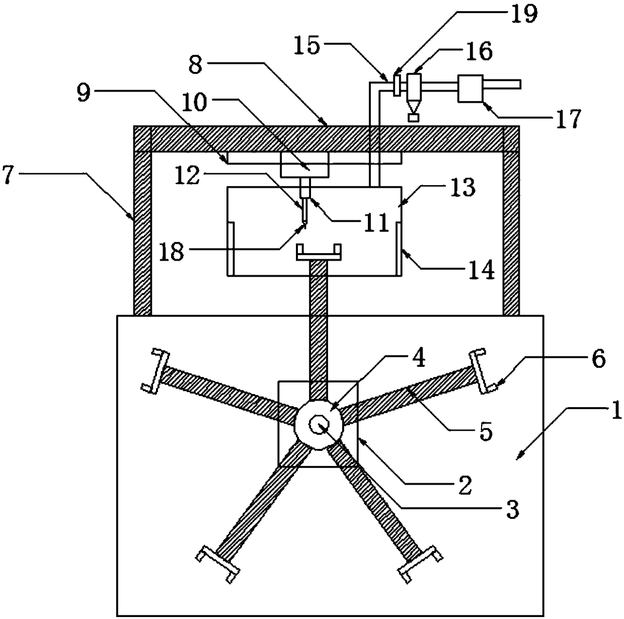
[0016] Such as figure 1 As shown, a rotary feeding welding device of the present invention includes a worktable 1, a servo motor 2, a rotating shaft 3, a rotary table 4, a connecting arm 5, a fixed table 6, a bracket 7, a beam 8, an electric slide rail 9, an electric Sliding table 10, cylinder 11, piston rod 12, protective cover 13, opening 14, exhaust gas discharge pipe 15, welding torch 18;

[0017] The servo motor 2 is set on the workbench 1, the rotating shaft 3 is fixedly arranged on the output shaft of the servo motor 2 through a coupling, the rotary table 4 is fixedly arranged at the end of the rotating shaft 3, and several connecting arms are evenly distributed on the rotary table 4 5. The end of any connecting arm 5 is fixed with a fixed platform 6, and the fixed platform 6 is provided with a fixture for fixing the parts to be welded;

[0018] Crossbeam 8 ...


PUM


Abstract

The invention provides a welding device capable of achieving rotational feeding. A servo motor is arranged on a workbench. A rotating shaft is fixedly arranged on an output shaft of the servo motor through a coupling. A round rotating table is fixedly arranged at the tail end of the rotating shaft. Multiple connecting arms are uniformly distributed at the rim of the rotating table. A fixing tableis fixedly arranged at the tail end of any connecting arm. Each fixing table is provided with a clamp used for fixing a to-be-welded part. A cross beam is arranged at the top end of the workbench through a support. An electric slide rail is arranged at the bottom end of the cross beam and provided with an electric slide table, wherein the electric slide table is connected with the electric slide rail in a sliding manner. An air cylinder is fixed to the bottom end of the electric slide table. A piston rod is arranged on the air cylinder, wherein the piston rod extends downwards vertically. A welding gun is arranged at the tail end of the piston rod. When the rotating table rotates, the fixing tables can be conveyed to the bottom end of the welding gun. The welding device has the beneficialeffects that ceaseless operation can be achieved, and the operation efficiency is high.

Description

technical field [0001] The invention belongs to the technical field of welding equipment, and in particular relates to a rotary feeding welding device. Background technique [0002] When the existing welding equipment is performing welding operations, it is necessary to fix the parts to be welded on the fixture first, and then perform welding after the material is loaded. A kind of rotary feeding welding device that can solve this problem and realize continuous uninterrupted operation still needs further research and development. Contents of the invention [0003] The object of the present invention is to provide a rotary feeding welding device with simple structure, simple operation and high working efficiency. [0004] The technical solution of the present invention is: a rotary feeding welding device of the present invention, including a worktable, a servo motor, a rotating shaft, a rotary table, a connecting arm, a fixed table, a bracket, a beam, an electric slide rai...

Claims


Application Information

Patent Timeline
Patent Type & Authority Applications(China)
IPC IPC(8): B23K37/00B23K37/047B08B15/00
CPCB23K37/00B08B15/007B23K37/047
Inventor 刘建兴刘益帮
Owner TIANJIN HAOHANG COMPOSITE PIPE
Why Eureka
Try Eureka