Confocal microscope mode aberration correction method

A confocal microscope and aberration technology, which is applied in the direction of measuring devices, instruments, and material analysis through optical means, can solve problems such as focal spot distortion, resolution reduction, aberration, etc., and achieve device overcoming, imaging quality improvement, The effect of resolution and image amplitude enhancement

Active Publication Date: 2018-05-29
HARBIN INST OF TECH +1
View PDF3 Cites 6 Cited by
  • Summary
  • Abstract
  • Description
  • Claims
  • Application Information

AI Technical Summary

Problems solved by technology

[0003] The purpose of the present invention is to provide a confocal microscope mode aberration correction method to solve the problem that the assembly error of the

Method used


Image

  • Confocal microscope mode aberration correction method
  • Confocal microscope mode aberration correction method
  • Confocal microscope mode aberration correction method

Examples


Embodiment Construction

[0028] Preferred embodiments of the present invention will be described in detail below with reference to the accompanying drawings.

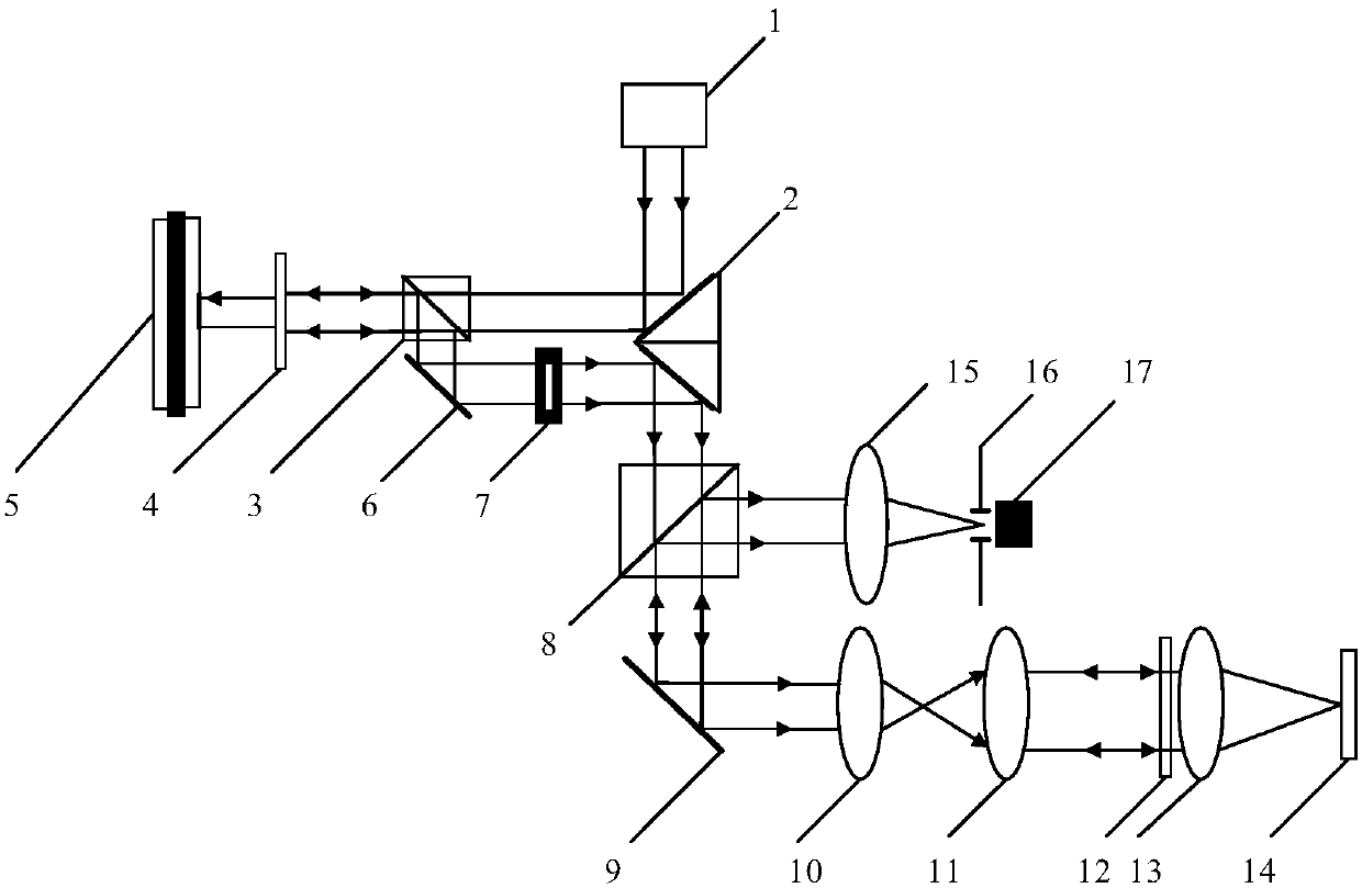
[0029] Such as figure 2 As shown, the confocal system on which the confocal microscope modal aberration correction method according to the present invention relies includes a laser 1, a double-sided 45° mirror 2, a beam splitter 3, a half-wave plate 4, and a spatial light modulation device 5, mirror 6, diaphragm 7, polarizing beam splitter 8, XY scanning galvanometer 9, scanning lens 10, tube mirror 11, objective lens 12, 1 / 4 wave plate 13, collecting lens 15, optical fiber aperture 16 and The photomultiplier tube 17, the laser light emitted by the laser 1 is reflected by one side of the double-sided 45° reflector 2, passes through the beam splitter 3, reaches the half-wave plate 4, and is modulated by the half-wave plate 4 before being injected into the spatial light modulator 5. After being modulated by the spatial light modulator 5, i...


PUM


Abstract

The invention relates to a confocal microscope mode aberration correction method and belongs to the adaptive optics and confocal microscopy imaging technological field. The invention aims to solve theproblems of focal spot distortion and resolution reduction caused by aberration which is further caused by the assembly error of an existing optical system and the surface shape deviation of opticalelements. According to the method, the fourth order to eleventh order of Zernike term bias aberrations of different amplitudes are loaded sequentially; the values of the gray-scale variance functionsof corresponding images are calculated; corresponding aberration coefficients are calculated through using a centroid method; comparison is performed, if the aberration coefficients are smaller than 0.7rad, zero clearing is performed, and other terms are pre-corrected; aberration coefficients are re-calculated through linear computation; and aberration correction is performed through using the sums of the coefficients obtained through the above two different times. According to the confocal microscope mode aberration correction method of the invention, wavefront distortion caused by the assembly error of the optical system and the surface shape deviation of the optical elements is compensated inversely through a spatial light modulator, and therefore, the aberration influence of a confocalmicroscope system can be effectively eliminated, and the imaging quality and resolution of the confocal microscope system can be enhanced.

Description

technical field [0001] The invention relates to a mode aberration correction method, in particular to a correction method for improving the quality and resolution of confocal imaging by using a confocal system, and belongs to the technical fields of adaptive optics and confocal microscopic imaging. Background technique [0002] Confocal microscopy has the advantages of high resolution and three-dimensional depth imaging. Its high-resolution characteristics require the focal spot size to be close to the diffraction limit to obtain the best theoretical resolution. However, the assembly error of the optical system and the surface deviation of the optical components will cause aberrations, resulting in distortion of the focal spot and loss of resolution. It is necessary to dynamically correct the aberrations generated by these optical systems to improve the imaging quality. At present, there is no simple and practical aberration correction method applied to confocal microscopy ...

Claims


Application Information

Patent Timeline
IPC IPC(8): G01M11/00G01N21/01
CPCG01M11/00G01N21/01
Inventor 刘辰光刘俭赵唯松陈刚谭久彬
Owner HARBIN INST OF TECH
Why Eureka
Try Eureka