Photon counting laser radar based on composite pseudo-random coding

A pseudo-random coding and photon counting technology, which is applied in the field of photon counting lidar, can solve the problems of low detection efficiency and the influence of dead time, and achieve the effects of reducing imaging time, reducing poor correlation, improving anti-noise ability and ranging performance

Active Publication Date: 2018-05-29
INST OF OPTICS & ELECTRONICS - CHINESE ACAD OF SCI
View PDF10 Cites 24 Cited by
  • Summary
  • Abstract
  • Description
  • Claims
  • Application Information

AI Technical Summary

Problems solved by technology

[0003] The invention aims to solve the problem that the traditional pseudo-random code photon counting laser radar is affected by the dead time of the GM-APD single photon detector, and the detection efficiency is low. The invention provides a photon counting laser radar based on a composite pseudo-random code

Method used


Image

  • Photon counting laser radar based on composite pseudo-random coding
  • Photon counting laser radar based on composite pseudo-random coding

Examples


specific Embodiment approach 1

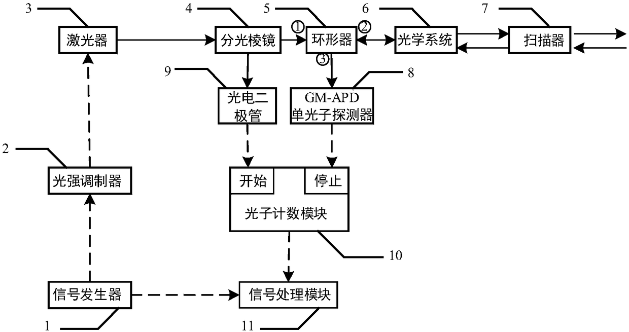
[0018] Specific implementation mode one: see figure 1 Describe this embodiment, a photon counting laser radar based on composite pseudo-random coding described in this embodiment, it includes a signal generator 1, a light intensity modulator 2, a laser 3, a beam splitting prism 4, a circulator 5, an optical system 6. Scanner 7, GM-APD single photon detector 8, photodiode 9, photon counting module 10, signal processing module 11;

[0019] Described signal generator 1 produces the pulse signal output end of composite pseudo-random code and is connected with the signal input end of light intensity modulator 2 and the signal input end of signal processing module 11 simultaneously, and the composite code output end of light intensity modulator 2 is connected with The input end of the laser 3 is connected, the pulse signal output end of the laser device 3 is connected with the input end of the beam splitting prism 4, an output end of the beam splitting prism 4 is connected with the ...

specific Embodiment approach 2

[0020] Specific implementation mode two: see figure 2 Describe this embodiment, the difference between this embodiment and the composite pseudo-random code-based photon counting lidar described in the first embodiment is that the specific process of the signal generator module is as follows:

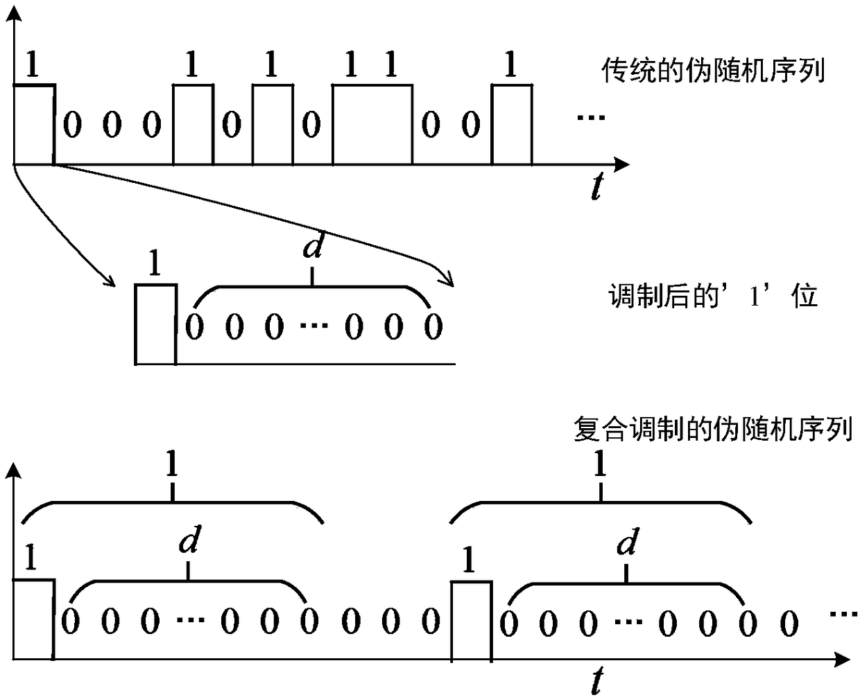
[0021] First, according to the principle of pseudo-random coding, a traditional pseudo-random sequence is generated. The traditional pseudo-random sequence contains two types of codes '0' and '1', and these two types of codes have the same symbol width, so The above-mentioned '0' code represents not emitting laser pulses, and the above-mentioned '1' represents emitting laser pulses;

[0022] Secondly, the '1' code in the traditional pseudo-random sequence is modulated, and the modulation method is to change all the '1' codes in the traditional pseudo-random sequence into one actual '1' code corresponding to the dead time length Composed of several '0' codes, no modulation is performed ...

specific Embodiment approach 3

[0024] Embodiment 3: The difference between this embodiment and the photon counting laser radar based on composite pseudo-random coding described in Embodiment 2 is that the modulated laser pulse described in Embodiment 2 realizes specific distance measurement through the radar system. The process is:

[0025] The composite pseudo-randomly modulated laser sequence generated by the second specific embodiment forms a transceiver with synchronous triggering of optical signals through the beam splitter, circulator, optical system, scanner, GM-APD single photon detector and photodiode. In the optical measurement system of the road, a part of the light is irradiated by the beam splitting prism to the photosensitive surface of the photodiode to get a synchronous trigger of an optical signal, and the other part of the light is emitted to the target through the ring, optical system, and scanner, and then reflected by the target and returned to the original path. The second port ② of th...


PUM


Abstract

The invention discloses a photon counting laser radar based on composite pseudo-random coding. The photon counting laser radar is composed of a signal generator, a light intensity modulation device, alaser device, a beam splitter prism, a circulator, an optical system, a scanner, a GM-APD single-photon detector, a photodiode, a photon counting module, and a signal processing module. An overall structure of a transmitting-receiving-same-path type optical reduced system is employed and a scanner is used for carry out scanning and transmitting a laser pulse string, so that the field angle of thelaser radar is extended. After processing on a laser signal transmitted by an optical system by the beam splitter prism, one part of the signal irradiates the photodiode directly to form a light trigger signal and the other part of signal is scanned by the scanner and then the scanned signal is irradiated on a target; an echo signal reflected by the target enters the scanner, the processed signalreturns to a second port of the circulator by the optical signal and enters the GM-APD single-photon detector through a third port of the circulator; the GM-APD single-photon detector records an echosequence and generates a stopping signal; and a detection result recorded by the photon counting module is transmitted to the signal processing module for follow-up processing and flight time of a pulse string is obtained.

Description

technical field [0001] The invention relates to the technical field of laser radar, in particular to a photon counting laser radar based on composite pseudo-random coding. Background technique [0002] Pseudo-randomly coded photon counting lidar uses GM-APD as a detector, which has single-photon detection capability and can measure long-distance weak signal targets. The signal-to-noise ratio of the radar signal, on the other hand, can obtain the target distance in one detection without multiple accumulations, which greatly reduces the imaging time and can detect high-dynamic targets. Therefore, it has attracted the attention of scientific researchers and has become a laser radar. research hotspots. However, GM-APD has an unavoidable shortcoming, that is, it has a dead time on the order of nanoseconds or even microseconds. The existence of this dead time greatly reduces the detection efficiency of traditional pseudo-random codes as transmitted pulses. Contents of the inven...

Claims


Application Information

Patent Timeline
Patent Type & Authority Applications(China)
IPC IPC(8): G01S17/10G01S7/484G01S7/486
CPCG01S7/484G01S7/486G01S17/14
Inventor 于洋刘博陈臻王华闯赵彬
Owner INST OF OPTICS & ELECTRONICS - CHINESE ACAD OF SCI
Why Eureka
Try Eureka