Portable computer hinge shell manufacturing method

A manufacturing method and a technology for a laptop computer, which are applied in the fields of electrical digital data processing, anodizing, instruments, etc., can solve the problems of inability to meet diverse needs, difficult to achieve aesthetic requirements, and large core draft angle, and achieve aesthetic appearance. Better fit, flawless joints and greater depth of weld

Inactive Publication Date: 2018-06-01
KUNSHAN WISPREN ELECTRONICS TECH CO LTD
View PDF3 Cites 4 Cited by
  • Summary
  • Abstract
  • Description
  • Claims
  • Application Information

AI Technical Summary

Problems solved by technology

[0003] At present, the rotating shaft part used to connect the laptop display and keyboard body is a zinc alloy stamping part. Because it is the connecting key of the laptop display and keyboard, and is exposed, the appearance requirements are high and the colors are diverse. However, stamping is very difficult. It is difficult to meet the appearance requirements: there are parting lines on the surface, and bubbles will be generated during electroplating treatment; the product shell is deep, stamped, and the core draft angle is large, it is difficult to meet the vertical aesthetic requirements, and the surface treatment is currently only Can be electroplated, but cannot meet diverse needs
[0004] In addition, the Chinese patent "Laptop wiring structure in the shaft compartment", application number 201310057297.0, application publication number CN 103149988 A, only discloses "including the notebook shaft compartment, and a pair of inwardly opened clamping wires are symmetrically arranged inside the shaft compartment." The door, the wire clamping door or the wire clamping door and the inner wall of the shaft compartment are used to set the wiring position", which focuses on the wiring structure of the shaft compartment, and does not solve the above problems

Method used


Image

  • Portable computer hinge shell manufacturing method
  • Portable computer hinge shell manufacturing method
  • Portable computer hinge shell manufacturing method

Examples


Embodiment 1

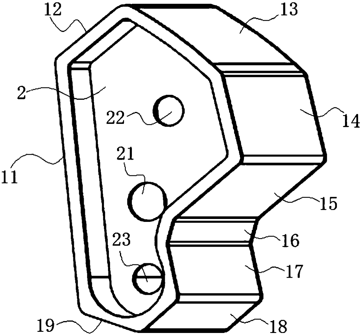
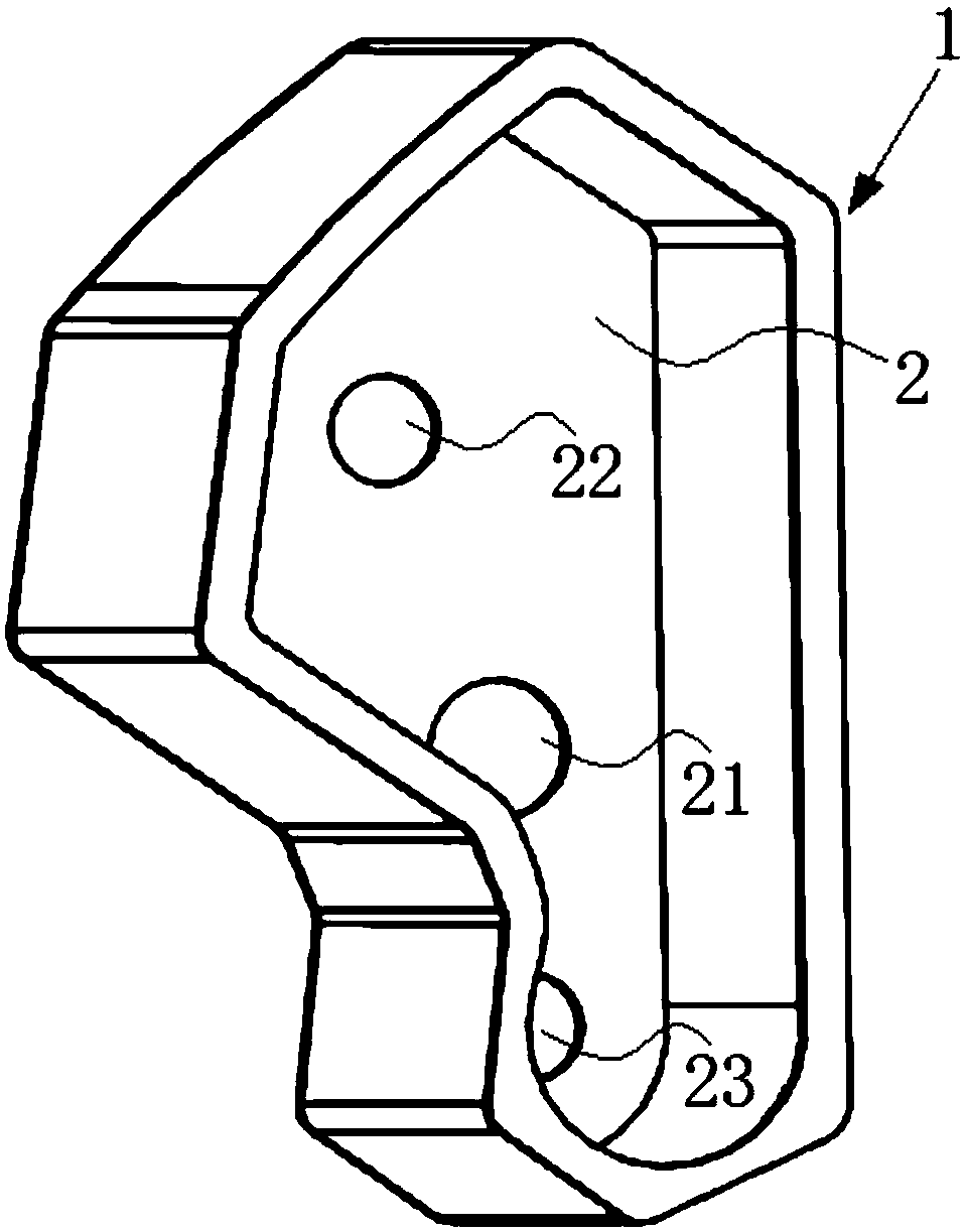
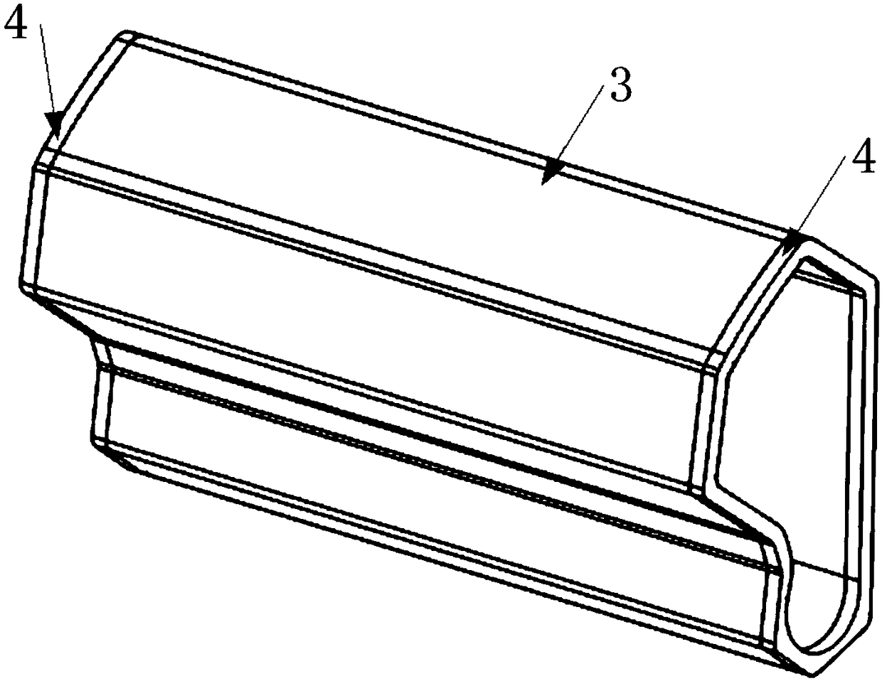
[0080] Embodiment 1: the product 1 that adopts described manufacturing method to produce below is: as Figure 1.1 to Figure 5 As shown, it includes a cylindrical shell 1 and a baffle 2 arranged in the cylindrical shell, an accommodating space is formed in the cylindrical shell, and the baffle is connected with the inner wall of the cylindrical shell by spot welding And the baffle is perpendicular to the inner wall of the cylindrical shell, and the edge of the baffle is closely attached to the inner wall of the cylindrical shell, and the outer surface and the middle part of the cylindrical shell are sub- The light area 3, the outer surface of the cylindrical shell and the two ends of the matt area are bright light areas 4, and both the matt light area and the bright light area are formed by anodic oxidation to form an anodized film;

[0081] The cylindrical housing includes nine successively connected surfaces, which are respectively the first plane 11, the second plane 12, the...

Embodiment 2

[0112] Embodiment 2: the following is the product 2 that adopts described manufacturing method to produce: as Figure 6.1 to Figure 9 As shown, it includes a cylindrical shell 1 and a baffle 2 arranged in the cylindrical shell, an accommodating space is formed in the cylindrical shell, and the baffle is connected with the inner wall of the cylindrical shell by spot welding And the baffle is perpendicular to the inner wall of the cylindrical shell, and the edge of the baffle is closely attached to the inner wall of the cylindrical shell, and the outer surface and the middle part of the cylindrical shell are sub- The light area 3, the outer surface of the cylindrical shell and the two ends of the matt area are bright light areas 4, and both the matt light area and the bright light area are formed by anodic oxidation to form an anodized film;

[0113] The cylindrical housing includes nine surfaces connected in sequence and are respectively the first plane, the second plane, the t...


PUM

PropertyMeasurementUnit
thicknessaaaaaaaaaa
thicknessaaaaaaaaaa
thicknessaaaaaaaaaa

Abstract

The invention discloses a portable computer hinge shell manufacturing method. A hinge shell comprises a cylindrical shell body and a baffle sheet arranged in the cylindrical shell body; an accommodation space is formed in the cylindrical shell body; and the baffle sheet is connected with the inner wall of the cylindrical shell body in a spot welding manner and is perpendicular to the inner wall ofthe cylindrical shell body. The manufacturing method comprises the following processes of stamping the baffle sheet; performing CNC machining on the cylindrical shell body; welding the edge of the baffle sheet to the inner wall of the cylindrical shell body in a laser spot welding manner; polishing the outer surface of the cylindrical shell body; forming a printing ink layer on the outer surfaceof the cylindrical shell body; performing laser carving to remove printing ink: performing the laser carving to remove the printing ink layer of a matte region; performing abrasive blasting on the outer surface of the cylindrical shell body; performing cleaning to remove the printing ink; and performing anodic oxidation. The hinge shell manufactured by adopting the method is simple in structure, attractive in appearance, convenient in machine shaping and high in degree of matching with a hinge of a portable computer; after installation, the hinge does not get loose and is high in matching degree and stable in rotation; the baffle sheet is connected with the cylindrical shell body through laser spot welding, so that no residues are generated; and the method is suitable for high-end portableproducts.

Description

technical field [0001] The invention belongs to the technical field of laptop computer rotating shaft processing, and in particular relates to a manufacturing method of a laptop computer shell. Background technique [0002] With the development of science and technology, various electronic products continue to appear, which bring great changes to people's lives, especially the use of computers has changed people's lifestyles and accelerated their pace of life. In the past two decades, with the development of material science and the emergence of smaller integrated chips, computers have evolved into a portable computer that is small in size, thin in thickness, light in weight and easy to carry around. Most of the existing portables are flip-top type. In order to meet the design considerations of thinness, small size and light weight, they are generally designed to be composed of two parts: the base composed of the host body and the keyboard, and the upper cover composed of th...

Claims


Application Information

Patent Timeline
Patent Type & Authority Applications(China)
IPC IPC(8): G06F1/16B23P15/00C25D11/08
CPCG06F1/1656B23P15/00C25D11/08G06F1/1675
Inventor 吴红兵
Owner KUNSHAN WISPREN ELECTRONICS TECH CO LTD
Why Eureka
Try Eureka