
Rotary Shaft Double-head Central Hole Vertical Grinder

A center hole and rotary shaft technology, used in the field of center hole grinding equipment, can solve the problems of difficulty in ensuring the center hole grinding quality, incomplete grinding of the center hole oxide layer, unreliable grinding quality, etc. The effect of labor intensity and simple structure

Pending Publication Date: 2018-06-05
CHENGDU AIRCRAFT INDUSTRY GROUP
View PDF8 Cites 5 Cited by
  • Summary
  • Abstract
  • Description
  • Claims
  • Application Information

AI Technical Summary

Problems solved by technology

Use corundum for rough grinding. When the grinding is finished, use a 20W or 14W chromium oxide grinder for fine grinding. This grinding method is labor-intensive, time-consuming and labor-intensive, and the work efficiency is low.
The center hole is often used as a benchmark in the process of processing and testing, so the quality of the center hole is directly related to the dimensional accuracy and shape position accuracy of each part of the machined shaft parts, while the traditional manual grinding method grinds the oxide layer of the center hole at both ends of the shaft Incomplete and uneven, it is difficult to ensure the grinding quality of the center hole, and it is easy to cause large jumps and large errors during processing, which will lead to out-of-tolerance or scrapped parts, and delay production
Especially for the center hole grinding of large quantities of shaft parts, because the traditional grinding method has the problems of low grinding efficiency and unreliable grinding quality, it is difficult to meet the needs of current production

Method used


Image

  • Rotary Shaft Double-head Central Hole Vertical Grinder
  • Rotary Shaft Double-head Central Hole Vertical Grinder
  • Rotary Shaft Double-head Central Hole Vertical Grinder

Examples


Embodiment Construction

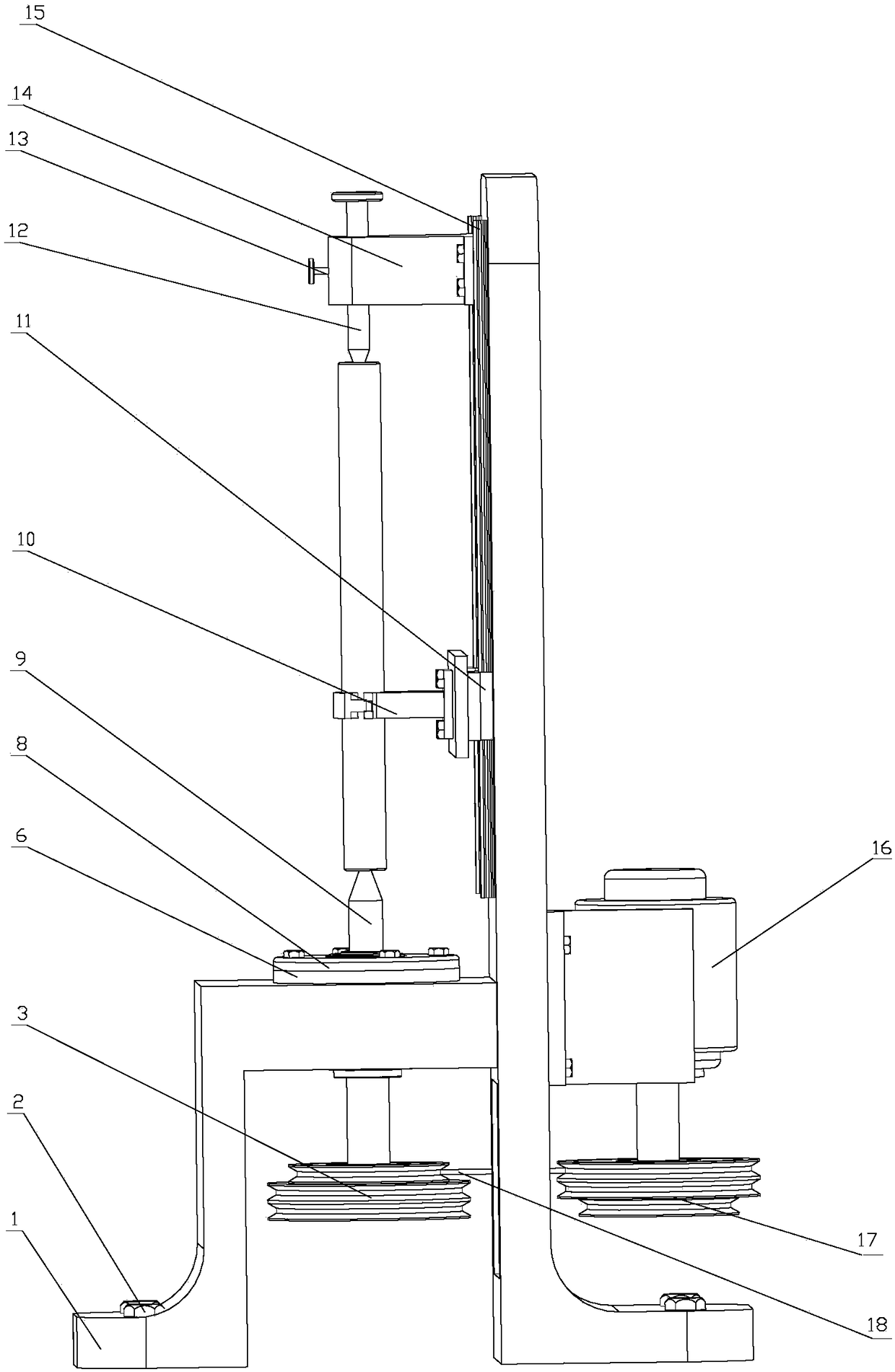
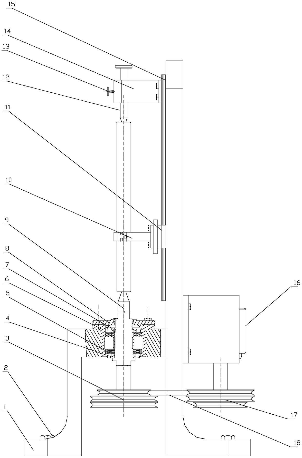
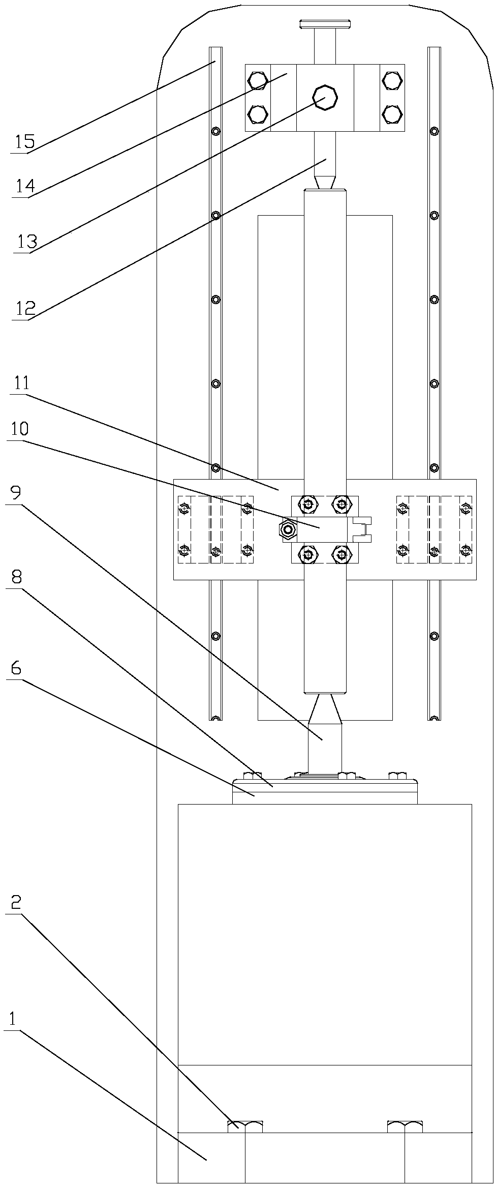
[0016] refer to Figure 1-Figure 3 . In the embodiment described below, a rotary shaft double-headed center hole vertical grinding machine has a π-shaped base 1 and a column plate vertical to the π-shaped base 1 in space, and the π-shaped The base 1 is fixed on the working ground, and the motor gearbox 16 fixed on the non-working surface of the column plate, the pulley 17 assembled on the main shaft of the motor gearbox 16 passes through the hollow of the lower part of the column plate through the transmission belt 18 Holes are connected to the pulley 3 located below the rectangular frame of the π-shaped base 1. The connecting shaft of the belt pulley 3 is provided with an active top 9, and the active top 9 passes through the rolling bearing assembled on the platform of the π-shaped base 1 and the bushing end cover 8 vertically upwards, the bushing 6 is assembled in the transmission hole of the π-shaped base, and the rolling bearing The outer circle of 5 fits in the inner ho...


PUM


Abstract

The invention discloses a rotary shaft double-head central hole vertical grinder, and aims to provide a vertical grinding device which has the advantages of simple structure, convenient operation andhigh efficiency, and can be adjusted according to the size and the length of different shafts. The invention will be realized according to the following technical scheme: an active center (9) is formed on the connecting shaft of the belt wheel (3), the active center is vertically upwards through a rolling bearing assembled by the pi-shaped base (1) platform and its bushing end cover (8), bearing the center hole of one end of shaft workpiece, the shaft-like workpiece is connected to a clamping device (10) on the slide rail (15) of the upright post by sliding method, and the central hole at theother end is coaxial with the tail seat rotary tip (12) of the tail seat bracket (14) above the upright post plate. The invention solves the problem that the traditional manual grinding mode has incomplete grinding and uneven grinding quality on the central hole oxide layer at two ends of the shaft and that it is difficult to guarantee the grinding quality of the central hole, large center jumpingand large error, and is easy to cause the problem of super-difference or rejection of the shaft parts.

Description

technical field [0001] The invention relates to a center hole grinding device mainly used for processing and manufacturing shaft parts in industries such as machine tool spindles, gear shafts, high-pressure oil pump shafts, mold guide rods, precision instruments, and meters. Specifically, it is mainly used for grinding the center hole of the rotary shaft workpiece, especially after quenching, to tighten the holes on both ends of the shaft. Background technique [0002] The center hole is an important benchmark for machining shaft parts. Generally, after rough machining or heat treatment, grinding is often unavoidable. The center hole requires high precision and surface finish, and the center hole must be ground before processing. Repairing the center holes at both ends of the spindle is an important process related to the accuracy of the repair spindle. The quality of the center hole mainly refers to the angle, surface finish and roundness error. These three items have a ...

Claims


Application Information

Patent Timeline
Patent Type & Authority Applications(China)
IPC IPC(8): B24B5/14B24B41/02B24B41/06B24B47/12
CPCB24B5/14B24B41/02B24B41/062B24B41/065B24B47/12
Inventor 刘成
Owner CHENGDU AIRCRAFT INDUSTRY GROUP
Learn More