Annular multi-pipe embedded type cascade steam injection activation kiln device and control method and application thereof

A technology of steam injection and steam injection, applied in chemical instruments and methods, inorganic chemistry, carbon compounds, etc., can solve the problems of unreasonable distribution of steam injection, poor quality, and low product activation degree.

Pending Publication Date: 2018-06-05
ZHONGYE-CHANGTIAN INT ENG CO LTD
View PDF4 Cites 1 Cited by
  • Summary
  • Abstract
  • Description
  • Claims
  • Application Information

AI Technical Summary

Problems solved by technology

[0006] 1. Insufficient contact between materials and steam: When the activation kiln in the prior art is in production, the steam sprayed into the kiln by the steam pipe at the kiln head box cannot be effectively sprayed to the middle and rear of the kiln, and even at the front of the kiln , the steam can only effectively contact the material on the surface of the kiln, but cannot fully react with the material on the lower layer
This will lead to insufficient contact between the whole material in the kiln and the steam, resulting in low product activation and poor quality;
[0007] 2. The distribution of steam injection volume is unreasonable: the activation kiln under the existing technology has only one steam inlet during production, and it is impossible to realize the cascaded gas distribution formed according to the temperature distribution in the kiln interval
This will lead to a situation where there is too much steam in some places and not enough steam in some places in the kiln, which will adversely affect production.

Method used


Image

  • Annular multi-pipe embedded type cascade steam injection activation kiln device and control method and application thereof
  • Annular multi-pipe embedded type cascade steam injection activation kiln device and control method and application thereof
  • Annular multi-pipe embedded type cascade steam injection activation kiln device and control method and application thereof

Examples


Embodiment 1

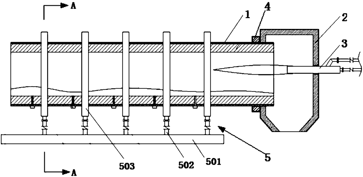
[0084] Such as figure 1 and 2 As shown, an annular multi-pipe pre-buried cascaded steam activation kiln device includes a kiln body 1, a kiln head box 2, a burner 3, a driving device 4, and a steam injection device 5. The end of the kiln body 1 is connected and communicated with the kiln head box 2 . The burner 3 is arranged on the axial side wall of the kiln head box 2. The driving device 4 is connected with the kiln body 1 and drives the kiln body 1 to rotate. The kiln body 1 is provided with an activation chamber 101 . The steam injection device 5 includes a steam delivery main pipe 501 , a steam delivery branch pipe 502 , a steam delivery ring 503 , and a steam injection pipe 504 . The steam conveying ring 503 is arranged concentrically with the kiln body 1 outside the kiln body 1 . One end of the steam injection pipe 504 passes through the kiln body 1 and communicates with the activation chamber 101 , and the other end of the steam injection pipe 504 is connected and...

Embodiment 2

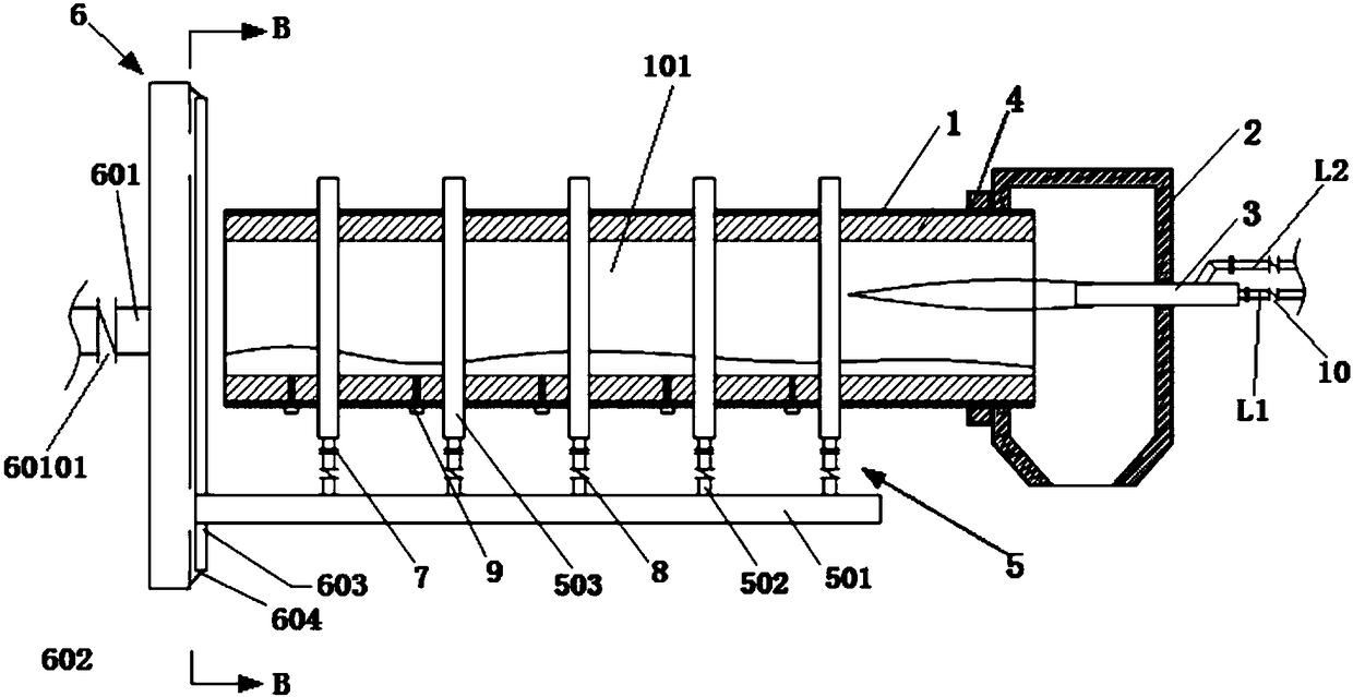
[0086] Such as image 3 and 4 As shown, embodiment 1 is repeated, except that the device also includes a static and dynamic sealing device 6 . The static and dynamic sealing device 6 includes an air supply main pipe 601 , a static disk 602 , a dynamic disk 603 and a seal 604 . The air supply manifold 601 is connected and communicated with the static disk 602 . The static disk 602 and the dynamic disk 603 are arranged in parallel, and a seal 604 is provided between the static disk 602 and the dynamic disk 603 . The dynamic disk 603 is fixedly connected with the steam delivery main pipe 501 . The static disk 602 is a hollow circular pie-shaped structure. The side of the static disk 602 close to the dynamic disk 603 is provided with an annular steam outlet 60201 . The inlet end of the steam delivery main pipe 501 corresponds to the position of the annular steam outlet 60201. The air supply main pipe 601 is provided with a main pipe control valve 60101 .

Embodiment 3

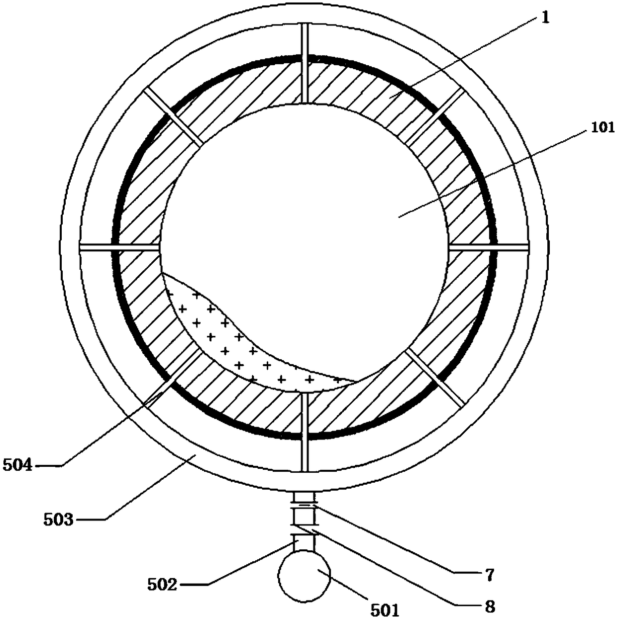
[0088] Repeat Example 2, except that the steam spraying device 5 includes five steam delivery rings 503 . The five steam delivery rings 503 are arranged concentrically with the kiln body 1 in the axial direction and evenly parallel to the outside of the kiln body 1 . Each steam delivery ring 503 is connected and communicated with the steam delivery main pipe 501 through an independent steam delivery branch pipe 502 . Each steam delivery ring 503 is provided with 6 steam injection pipes 504. One end of the 6 steam injection pipes 504 is evenly arranged on the kiln body 1, and the other end of each steam injection pipe 504 is connected with the steam delivery ring 503 and connected.


PUM


Abstract

An annular multi-pipe embedded type cascade steam injection activation kiln device comprises a kiln body, a kiln head box, a burner, a drive device and a steam injection device. The tail end of the kiln body is connected with and communicates with the kiln head box. The burner is arranged on the side wall of the kiln head box. The drive device is connected with the kiln body and drives the kiln body to rotate. An activation chamber is arranged in the kiln body. The steam injection device comprises a steam conveying header pipe, a steam conveying branch pipe, a steam conveying ring and a steaminjection pipe. The steam conveying ring is arranged on the outer side of the kiln body in a surrounding mode. One end of the steam injection pipe penetrates through the kiln body to communicate withthe activation chamber. The other end of the steam injection pipe is connected with and communicates with the steam conveying ring. The steam conveying ring is connected with and communicates with thesteam conveying header pipe through the steam conveying branch pipe. According to the activation kiln device, steam injection inlets are formed in a kiln body, the number is increased substantially,and steam is injected in a segmental independent-control mode; and the contact specific surface area of materials in the kiln and steam is increased substantially, and thus the activation grade of products is improved effectively.

Description

technical field [0001] The invention relates to an activation kiln device, in particular to an activation kiln device injecting steam, a control method and application thereof, and belongs to the field of construction equipment. Background technique [0002] Rotary kiln, also known as rotary calcining kiln, is a large-scale equipment in the core industry, which is widely used in building materials, metallurgy, chemical industry, environmental protection and other production industries. Its function is to use rotation and internal high temperature to calcine the materials in the kiln to form finished ore. Rotary kiln can be divided into cement kiln, metallurgical chemical kiln and lime kiln according to different materials. Cement kilns are mainly used for calcining cement clinker, which can be divided into two categories: dry production cement kiln and wet production cement kiln. Metallurgical and chemical kilns are mainly used for magnetization roasting of lean iron ore i...

Claims


Application Information

Patent Timeline
Patent Type & Authority Applications(China)
IPC IPC(8): F27B7/00F27B7/36C01B32/39C01B32/336
CPCF27B7/00F27B7/36
Inventor 周浩宇魏进超叶恒棣
Owner ZHONGYE-CHANGTIAN INT ENG CO LTD
Why Eureka
Try Eureka