Rotary injection type evaporation tube of combustion chamber of micro engine

A technology of rotary injection and evaporation tube, applied in the combustion chamber, continuous combustion chamber, combustion method, etc., can solve the problems of unstable combustion and unsatisfactory mixing degree, and achieve the effect of simple structure, easy processing and sufficient combustion

Inactive Publication Date: 2018-06-08
NORTHWESTERN POLYTECHNICAL UNIV
View PDF1 Cites 3 Cited by
  • Summary
  • Abstract
  • Description
  • Claims
  • Application Information

AI Technical Summary

Problems solved by technology

[0004] At present, the design types of the evaporator tube structure mainly include straight cylinder type and "L" type. The mixing degree of fuel and air in the combustion chamber through these two types of evaporator tubes is not ideal, and the combustion is not stable enough.

Method used


Image

  • Rotary injection type evaporation tube of combustion chamber of micro engine
  • Rotary injection type evaporation tube of combustion chamber of micro engine
  • Rotary injection type evaporation tube of combustion chamber of micro engine

Examples


Embodiment Construction

[0019] The present invention will be further described now in conjunction with accompanying drawing:

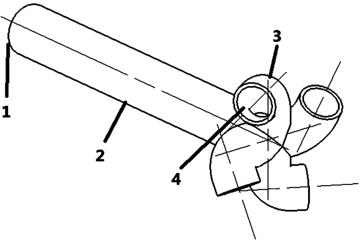
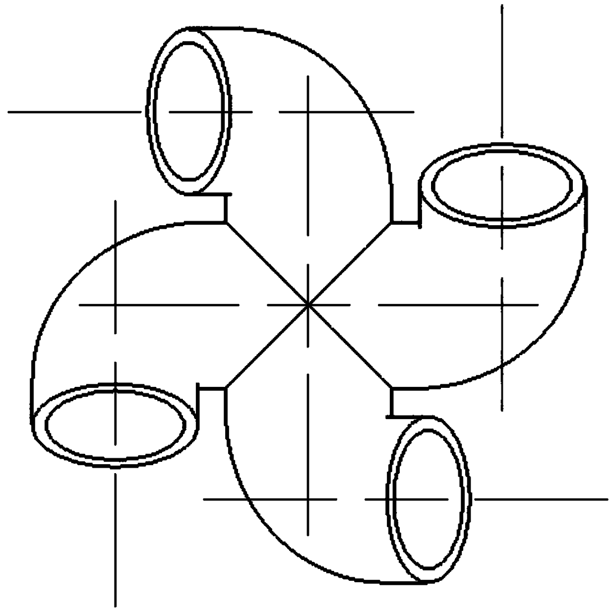
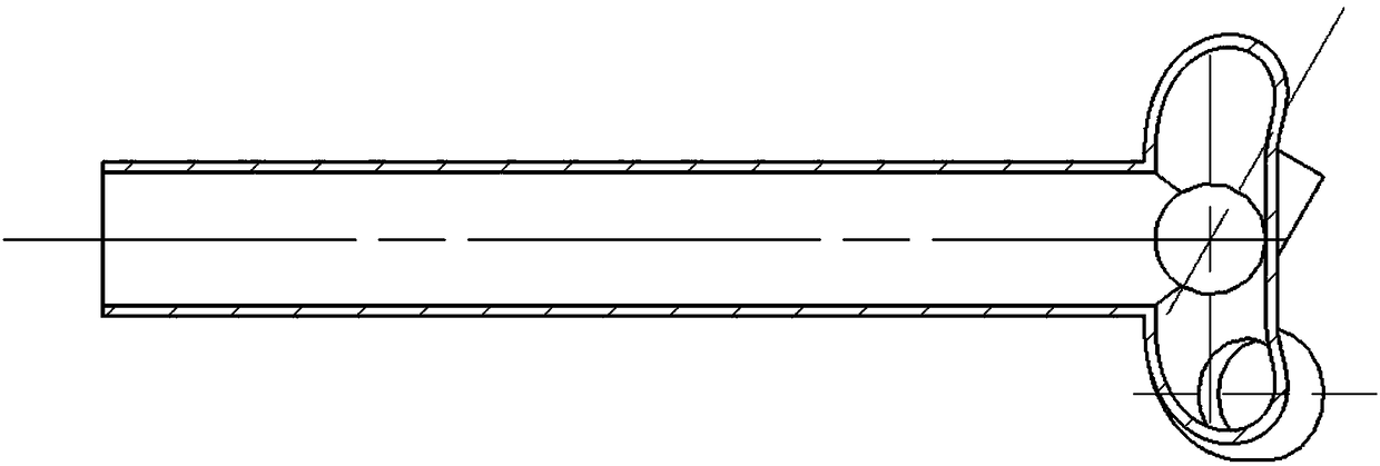
[0020] combine figure 1 , figure 2 and image 3 , The present invention provides a micro-engine combustor rotary jet evaporator tube structure that can increase the mixed degree of fuel and air and stabilize the air flow. figure 1 is the overall schematic diagram of the evaporation tube, figure 2 It is the right view of the evaporation tube seen from the direction of the nozzle, it can be clearly seen that the four rotating branch pipeline structures are connected to the evaporation tube vertically in turn, image 3 It is a cross-sectional view of the evaporation tube, and the connection between the branch pipeline structure and the inside of the evaporation tube can be seen.

[0021] according to figure 1 As shown, the mixed flow of fuel and air enters the evaporator tube (2) from the evaporator tube inlet (1), and in the evaporator tube (2), the fuel is heated and ev...


PUM

PropertyMeasurementUnit
Thicknessaaaaaaaaaa
Diameteraaaaaaaaaa

Abstract

The invention provides a rotary injection type evaporation tube structure of a combustion chamber of a micro engine. The structure can effectively improve the mixing degree of fuel in the micro combustion chamber and air, so that fuel distribution is more uniform, combustion is more sufficient, and the combustion efficiency is improved. By using four rotating branch pipeline structures at the tailend of an evaporation tube, air flows are sprayed out simultaneously from outlets of the four rotating branch pipeline structures and have evaporation tube axial speed and radial speed, the four airflows act on one another to form a rotational flow, and then the fuel-air mixing degree is improved; besides, a certain backflow area can be formed in the combustion chamber so that the air flows canbe stabilized, flame is more stable, and better combustion is promoted.

Description

technical field [0001] The invention belongs to the field of micro-engine combustion chambers, and in particular relates to a novel evaporating tube design which can effectively improve the mixing degree of fuel and air, make the distribution of fuel more uniform, stabilize air flow, and improve combustion efficiency. Background technique [0002] In recent years, micro power system has become a domestic research hotspot, and micro engine has also become one of the most promising powers. It has the advantages of small size, light weight, large output energy, and high density. The micro-combustion chamber is an important part of the micro-engine, and its design is also a key link in the design of the micro-engine. [0003] In the micro combustor, there are generally two oil supply methods: evaporator tube oil supply and centrifugal oil thrower oil supply. Among them, the evaporator tube oil supply is widely used because of its simple structure and high atomization efficiency...

Claims


Application Information

Patent Timeline
IPC IPC(8): F23R3/38
CPCF23R3/38
Inventor 张群海涵张鹏王鑫寇睿李承钰宋亚恒黎超超李逸飞
Owner NORTHWESTERN POLYTECHNICAL UNIV
Why Eureka
Try Eureka