Supercharge Your Innovation With Domain-Expert AI Agents!

General purpose input-output interface circuit and control method thereof

A general-purpose input and output, interface circuit technology, applied in the direction of electrical digital data processing, instruments, etc., can solve problems such as electromagnetic interference, GPIO circuit output logic error, output signal Uout voltage can not be reached, etc., to achieve simple structure, obvious effect, large The effect of practical value

Pending Publication Date: 2018-06-08
HANGZHOU SILAN MICROELECTRONICS
View PDF0 Cites 5 Cited by
  • Summary
  • Abstract
  • Description
  • Claims
  • Application Information

AI Technical Summary

Problems solved by technology

from Figure 2c It can be seen from the figure that when the driving capability of the GPIO circuit is too small, the output signal does not have time to follow the first internal data I_data to achieve inversion, so that the voltage of the output signal Uout cannot reach the inversion threshold and cause an error in the output logic of the GPIO circuit; from Figure 2d It can be seen from the figure that when the slew rate of the GPIO circuit is too small, the output signal Uout cannot reach the external high-level power supply voltage VDDA in a short period of time, nor can it follow the first internal data I_data in a short period of time. Falling to a low level, which will affect the response speed of the GPIO circuit; from Figure 2e It can be seen from the figure that when the driving capability of the GPIO circuit is too large, the output signal Uout will have a peak when it is reversed, which will cause large electromagnetic interference to the external circuit receiving the output signal

Method used


Image

  • General purpose input-output interface circuit and control method thereof
  • General purpose input-output interface circuit and control method thereof
  • General purpose input-output interface circuit and control method thereof

Examples


Embodiment Construction

[0061] Various embodiments of the invention will be described in more detail below with reference to the accompanying drawings. In the various drawings, the same elements are denoted by the same or similar reference numerals. For the sake of clarity, various parts in the drawings have not been drawn to scale.

[0062] The invention can be embodied in various forms, some examples of which are described below.

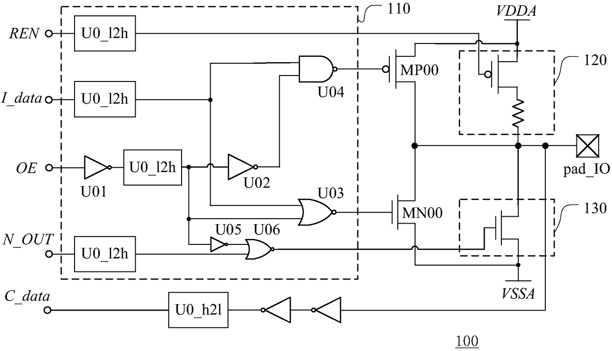
[0063] image 3 A schematic block diagram showing the general input and output interface circuit of the first embodiment of the present invention.

[0064] like image 3 As shown, the general input output interface (GPIO) circuit 1000 of the embodiment of the present invention includes a first channel CH_1, a second channel CH_2 and a bidirectional connection port pad_IO, and the GPIO circuit 1000 can be located inside a chip (such as an SOC chip, etc.) to pass The connection port pad_IO realizes the exchange between the internal signal of the chip and the external sig...


PUM


Abstract

The invention discloses a general purpose input-output interface circuit and a control method thereof. The general purpose input-output interface circuit comprises a first channel and a connection port, wherein the first channel is used for providing an output signal for the connection port according to first internal data. The general purpose input-output interface circuit is characterized in that the first channel comprises a control module and a driving module, wherein the control module is used for generating an output control signal according to the first internal data, the driving moduleis used for generating the output signal according to a mode selection signal and the output control signal, the level state of the output signal is controlled by the output control signal, the driving module has multiple driving modes, current intensity and / or slew rates of output signals corresponding to different driving modes are different, and the mode selection signal is used for selectingone of the driving modes. Through the general purpose input-output interface circuit and the control method thereof, by providing multiple driving modes with different driving abilities or slew rates,the general purpose input-output interface circuit can be suitable for different application scenes.

Description

technical field [0001] The invention relates to the field of integrated circuits, in particular to a general input and output interface circuit and a control method thereof. Background technique [0002] A General Purpose Input Output (GPIO) circuit is widely used in a System On Chip (SOC) and is mainly used for exchanging internal signals of the chip and external signals of the chip. The GPIO circuit is usually used to level shift and drive the data provided inside the chip to generate an external data signal, and / or level shift the data from outside the chip to obtain a data signal that can be recognized by the chip. At the same time, the GPIO circuit It also provides functions such as enable control, input and output control, and pull-up and pull-down control. [0003] figure 1 A schematic circuit diagram of a conventional GPIO circuit is shown. [0004] like figure 1 As shown, the conventional GPIO circuit 100 includes output channels and input channels. [0005] Th...

Claims


Application Information

Patent Timeline
IPC IPC(8): G06F13/38G06F13/40
CPCG06F13/385G06F13/4022
Inventor 虞峰张和平郑卫卫
Owner HANGZHOU SILAN MICROELECTRONICS
Features
  • R&D
  • Intellectual Property
  • Life Sciences
  • Materials
  • Tech Scout
  • Unparalleled Data Quality
  • Higher Quality Content
  • 60% Fewer Hallucinations
Learn More