Method and device for controlling an air drying unit of an air supply system for the primary and secondary air supply of a vehicle, in particular a rail vehicle

An auxiliary air and air-drying technology, which is applied in the direction of air treatment devices, vehicle subunit functions, chemical instruments and methods, etc., can solve the problems of refilling lag, lag, consumption, etc., and achieve the effect of quickly putting into use and shortening the maintenance time

Active Publication Date: 2020-09-22
KNORR BREMSE SYST FUR SCHIENENFAHRZEUGE GMBH
View PDF6 Cites 0 Cited by
  • Summary
  • Abstract
  • Description
  • Claims
  • Application Information

AI Technical Summary

Problems solved by technology

[0008] The disadvantage of the prior art is that during the auxiliary air supply, which is mainly used to refill the auxiliary air storage tank, dry compressed air is also consumed for regeneration of the air drying unit
As a result, there is a lag in the refilling of the auxiliary air storage tank, especially if this occurs in the context of the conditioning of rail vehicles with pantograph supply, since the process used to establish the operational readiness of the vehicle (i.e. pantograph extension) is further delayed in case of battery operation of the auxiliary air supply system

Method used


Image

  • Method and device for controlling an air drying unit of an air supply system for the primary and secondary air supply of a vehicle, in particular a rail vehicle
  • Method and device for controlling an air drying unit of an air supply system for the primary and secondary air supply of a vehicle, in particular a rail vehicle
  • Method and device for controlling an air drying unit of an air supply system for the primary and secondary air supply of a vehicle, in particular a rail vehicle

Examples


Embodiment Construction

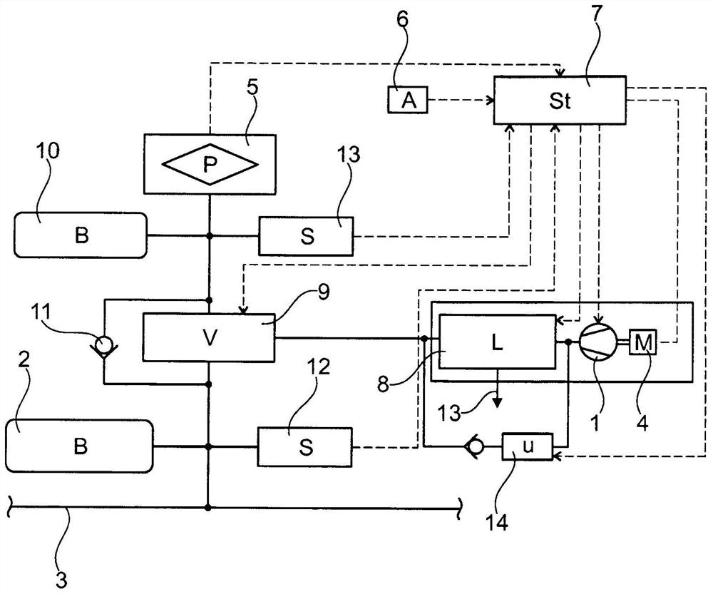
[0024] according to figure 1 , in the area of ​​the main and auxiliary air supply of the electric rail vehicle (not further shown) a compressor 1 is arranged to generate a main air storage tank 2 for filling and a main air storage tank line 3 connected thereto of compressed air. The compressor 1 is driven by an electric motor 4 . During normal operation of the rail vehicle, the electrical energy for driving the electric motor 4 is harvested via the pantograph 5 via the overhead conductor connection. The on-board battery 6 provided on the vehicle is used for additional electrical energy supply. The electrical energy supply by means of the pantograph 5 and the on-board battery 6 is controlled via the electronic control unit 7 (dotted line), which in particular also contains an integrated converter to vary the voltage and frequency for driving the electric motor 4, which In this case, it is designed as a three-phase AC motor.

[0025] For retracting and extending the pantogra...


PUM


Abstract

The invention relates to a method and a device for controlling at least one air drying unit (8; 8a-8c) of an air supply system for a vehicle's primary and secondary air supply, wherein at least one air drying unit (8; 8a-8c) is controlled via an electric motor ( 4; 4a‑4c) driven compressor (1; 1a‑1c) implements both the main air supply to the main air storage tank (2) and the auxiliary air supply to the auxiliary air storage tank (10), the compressor The compressed air produced by (1; 1a-1c) is led through said at least one air drying unit (8; 8a-8c) connected downstream, with which the compressor (1; 1a-8c) is supplied by the compressor (1; 1a- 1c) Drying of the generated compressed air, i.e. regeneration of the desiccant of the air drying unit (8; 8a-8c) with the dried compressed air; wherein during the supply of auxiliary air the use for drying at least one air The unit (8; 8a-8c) regenerates the air flow so that in the auxiliary air supply compared to the main air supply, there is a higher volume flow or the volume flow provided by the compressor (1; 1a-1c) can be used for Fill the auxiliary air reservoir (10).

Description

technical field [0001] The invention relates to a method and a device for controlling at least one air drying unit of an air supply system for the main and auxiliary air supply of a vehicle, in particular a rail vehicle, whereby at least one via configured The electric motor-driven compressor implements both the main air supply to the main air storage tank and the auxiliary air supply to the auxiliary air storage tank, wherein the compressed air produced by the compressor is guided through the at least one An air drying unit with which the compressed air produced by the compressor is dried, wherein the desiccant used depending on the type of air drying unit is regenerated with the dried compressed air. Background technique [0002] The field of application of the invention extends mainly to rail vehicle construction. In this range, a compressor driven by an electric motor generates compressed air, which is used to supply pneumatic units, such as vehicle brakes. For this pu...

Claims


Application Information

Patent Timeline
Patent Type & Authority Patents(China)
IPC IPC(8): B60T17/02F15B21/04F15B21/048
CPCB60T17/02F15B21/048F15B2211/655F15B2211/7142F15B2211/80B01D53/261B01D53/268B01D2259/4566B60T17/004B60Y2400/81F15B21/04B01D53/26
Inventor T·默克尔P·贝格尔G·阿斯曼C·乌拉A·里迪P·格尔克
Owner KNORR BREMSE SYST FUR SCHIENENFAHRZEUGE GMBH
Why Eureka
Try Eureka