Normal-temperature low-dew-point runner dehumidification unit

A dehumidification and low dew point technology with a rotary wheel, which is applied in household heating, lighting and heating equipment, space heating and ventilation, etc. It can solve the problems of less adjustability of residual pressure, increased cooling consumption of middle and surface cooling, and easy leakage of airflow and other problems, to achieve the effect of more adjustable residual pressure, low leakage treatment and stable working conditions

Inactive Publication Date: 2018-03-06
浙江捷峰环境科技有限公司
View PDF3 Cites 6 Cited by
  • Summary
  • Abstract
  • Description
  • Claims
  • Application Information

AI Technical Summary

Problems solved by technology

like figure 1 As shown in , the current conventional low dew point dehumidification unit has the following disadvantages: 1. Single-process fan, local pressure head is too large, air flow is easy to leak, the system is unstable and noisy, and the residual pressure is less adjustable
2. The regeneration air is taken from the rear side of the middle surface cooling, and the cooling consumption of the middle surface cooling is effectively increased
3. The regeneration air is reduced by more than 20°C due to the ineffective cooling of the surface

Method used


Image

  • Normal-temperature low-dew-point runner dehumidification unit
  • Normal-temperature low-dew-point runner dehumidification unit

Examples


Embodiment Construction

[0018] In order to facilitate the understanding of the present invention, the present invention will be described in detail below in conjunction with the preferred embodiments of the present invention given in the accompanying drawings.

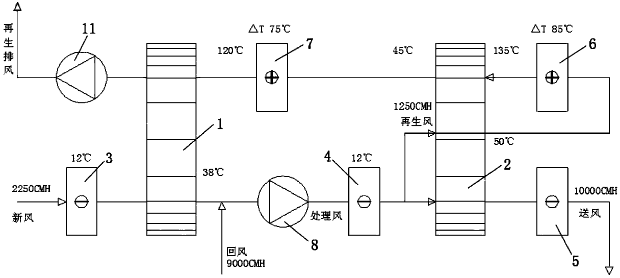
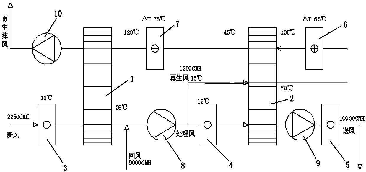
[0019] like figure 2 As shown, the normal temperature low dew point rotary dehumidification unit of the embodiment of the present invention includes a primary rotary heat exchanger 1, a secondary rotary heat exchanger 2, a front surface cooler 3, an intermediate surface cooler 4, and a rear surface cooler. 5, the primary regeneration heater 6 and the secondary regeneration heater 7, the primary rotary heat exchanger 1 is set separately for the primary treatment moisture absorption zone and the primary regeneration desorption zone, and the secondary rotary heat exchanger 2 is set separately Secondary treatment moisture absorption zone, secondary regeneration desorption zone and secondary regeneration cooling zone. As an example, the secondar...


PUM


Abstract

The invention discloses a normal-temperature low-dew-point runner dehumidification unit. The normal-temperature low-dew-point runner dehumidification unit comprises a first-level runner heat exchanger, a second-level runner heat exchanger, a front surface air cooler, a middle surface air cooler, a rear surface air cooler, a first-level regeneration heater and a second-level regeneration heater. Afirst-level treatment moisture absorbing area and a first-level regeneration desorption area are arranged in the first-level runner heat exchanger in a distinguished manner. A second-level treatment moisture absorbing area, a second-level regeneration desorption area and a second-level regeneration cooling area are arranged in the second-level runner heat exchanger in a distinguished manner. Freshair sequentially passes through the front surface air cooler and the first-level treatment moisture absorbing area to mix with return air to be divided into two paths, one path of mixed air sequentially passes through the middle surface air cooler, the second-level treatment moisture absorbing area and the rear surface air cooler to be conveyed to a drying area, and the other path of mixed air sequentially passes through the second-level regeneration cooling area, the first-level regeneration heater, the second-level regeneration desorption area, the second-level regeneration heater and the first-level regeneration desorption area and then is exhausted out of a room. The runner dehumidification unit is stable in airflow, the integral pipeline pressure is balanced, energy saving and consumption reducing are achieved, and the work condition is stable.

Description

technical field [0001] The invention relates to the technical field of rotary dehumidifiers, in particular to a normal temperature low dew point rotary dehumidifier unit. Background technique [0002] The adsorption rotary dehumidifier is recognized as one of the preferred technologies for CFC's compression refrigeration dehumidification due to its remarkable energy saving and environmental protection advantages. The rotary dehumidifier can quickly, easily and effectively reduce air humidity, and can utilize industrial waste heat , Waste heat, solar energy, natural gas and other low-grade thermal energy are renewable energy sources, without environmental pollution and low energy consumption. Widely used in food, medicine, electronics, electrical appliances, chemical industry and other industries with humidity requirements. like figure 1 As shown in , the current conventional low dew point dehumidification unit has the following disadvantages: 1. Single-process fan, local p...

Claims


Application Information

Patent Timeline
Patent Type & Authority Applications(China)
IPC IPC(8): F24F3/14
Inventor 慎华兵李锦洲葛鸿雁雷赤明
Owner 浙江捷峰环境科技有限公司
Why Eureka
Try Eureka