Floating vessel

A technology for motorboats and hulls, which is applied in the directions of ships, foldable/inflatable hulls, and safety of ships, can solve problems such as movement of mechanical adjustment devices, difficulty in installation and removal of cantilevers, and precise control of ships with different motor power settings. Achieve good reliability and little susceptibility to interference

Active Publication Date: 2018-06-08
CAYAGO
View PDF13 Cites 2 Cited by
  • Summary
  • Abstract
  • Description
  • Claims
  • Application Information

AI Technical Summary

Problems solved by technology

[0006] The disadvantage of known ships is the mechanical setting of the motor power
For this purpose, for example, Bowden cables or other mechanical adjustment devices have to be routed from the controller of the hull of the vessel to the motor in the jib, which makes mount

Method used


Image

  • Floating vessel
  • Floating vessel
  • Floating vessel

Examples


Embodiment Construction

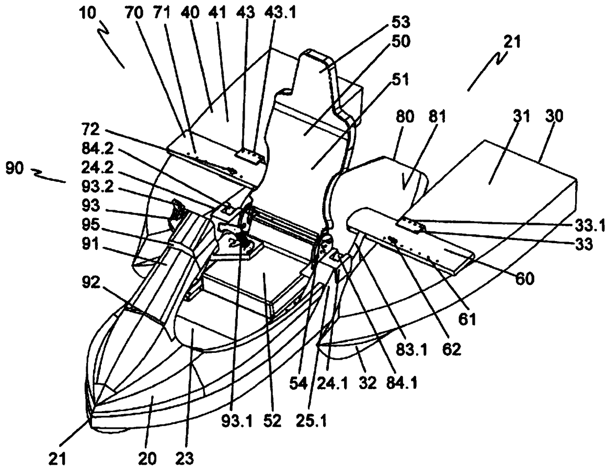
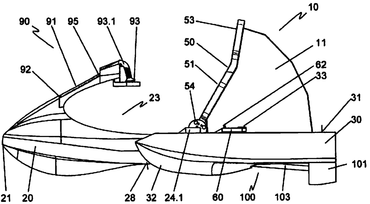
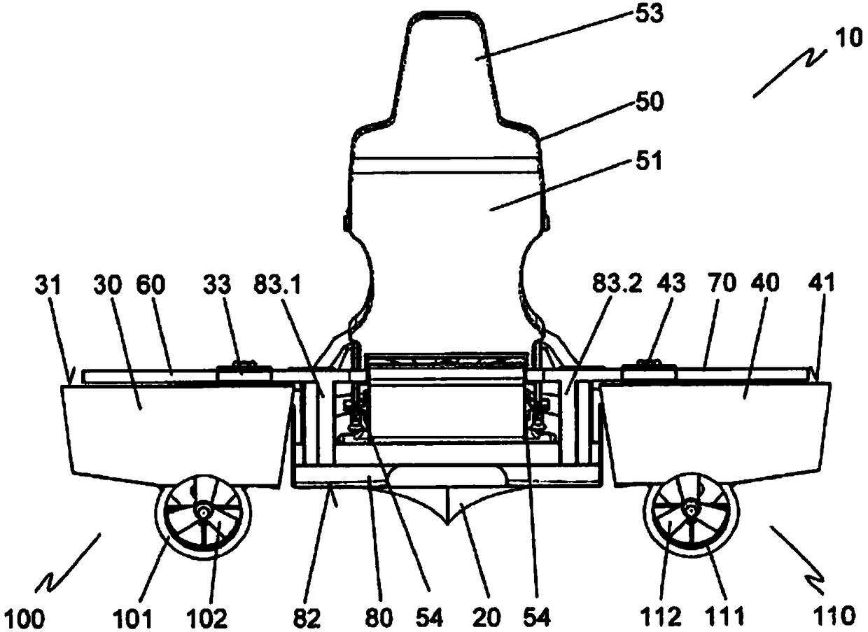
[0034] figure 1 Jet ski 10 is shown in perspective side view. The jet ski 10 is formed from a hull 20 and two suspension arms 20 , 30 arranged laterally and set back in the direction of a tail section 21 of the jet ski 10 relative thereto. The hull 20 carries a seat 50 having a seating surface 52 , a backrest 51 and a headrest 53 . The backrest 51 is hingedly connected to the seating surface 52 via a hinge connection 54 . In front of the seating surface 52 , the hull 20 forms a foot well 23 . A steering column 91 and a controller 93 are assigned to the control system 90 . Steering column 91 is directed obliquely upwardly towards seat 50 from bow 21 of watercraft 10 . The steering column 91 is connected at its end facing the bow 21 to the hull 20 via a folding connection 92 . On the other hand, the controller 93 is connected to the steering column 91 via the rotary joint 95 . In the variant shown, the controller 93 carries two control handles 93.1, 93.2, Image 6 The ope...


PUM


Abstract

The invention relates to a floating vessel comprising a hull, at least one seat, and two outriggers arranged laterally to the hull and connected directly or indirectly to the hull, wherein a drive unit, separately controllable in its drive output, and comprising a respective at least one propeller driven by a motor, in particular an electric motor, is assigned to each outrigger. A helm of the floating vessel is thereby connected to a proportional transducer, and a control signal from the proportional transducer is supplied to a control unit which directly or indirectly controls the motors in accordance with the control signal from the proportional transducer. Thus, a precisely controllable and yet easily disassemblable floating vessel is provided.

Description

technical field [0001] The invention relates to a jet ski having a hull, at least one seat and two booms arranged on the sides of the hull and connected indirectly or directly to the hull, wherein each boom is assigned its driving power Separately controllable drive units each have at least one propeller driven by a motor, in particular an electric motor. Background technique [0002] From the document US 2004 / 0168623 A1 (Multi-Hull Personal Watercraft) a watercraft for leisure is known which has two (catamaran) or more (trimaran) hulls and one or more seats. One or more outlet openings of the jet drive are provided for driving. The jet drive may be arranged between or in or on the hulls. For this purpose, the hull can be dimensioned such that all or some parts of the jet drive can be accommodated in the hull. For controlling the vessel, it is provided that the water jets of the outfalls are controlled independently of one another or in relation to one another via corresp...

Claims


Application Information

Patent Timeline
IPC IPC(8): B63B1/12B63B35/73B63H21/17G05B11/38B63B7/00
CPCB63B1/125B63H5/07B63H21/17B63B34/10B63B43/14B63H25/06G05B11/38B63B1/12B63H25/42B63H5/08B63H5/14
Inventor H-P·瓦普尔吉斯P·施瑙费尔
Owner CAYAGO
Why Eureka
Try Eureka