Sealed-type cavity welding connector structure and welding clamp and welding method thereof

A technology for welding joints and welding fixtures, applied in welding equipment, welding equipment, auxiliary welding equipment, etc., can solve the problems of easy generation of pores, collapse of welding seam, low product qualification rate, etc., and achieve the effect of improving work efficiency and ensuring accuracy

Pending Publication Date: 2018-06-12
HUNAN JOINFRONT WELDING TECH
View PDF9 Cites 2 Cited by
  • Summary
  • Abstract
  • Description
  • Claims
  • Application Information

AI Technical Summary

Problems solved by technology

The cavity and the cover plate are often made of different materials. If traditional fusion welding is used to weld them, defects such as air holes and large deformation are likely to occur, and the product qualification rate is low. High requirements and high processing costs
Friction stir welding can be used to weld dissimilar materials. The quality of the weld is good, less deformation, no pollution, and insensitive to ambient temperature and humidity. However, there are some problems and difficulties in welding closed cavity structures using friction stir welding.
The structure of the parts of the closed cavity is complicated, and it is often processed and produced by casting. Seam collapse, edge collapse and other defects

Method used


Image

  • Sealed-type cavity welding connector structure and welding clamp and welding method thereof
  • Sealed-type cavity welding connector structure and welding clamp and welding method thereof
  • Sealed-type cavity welding connector structure and welding clamp and welding method thereof

Examples


Embodiment 1

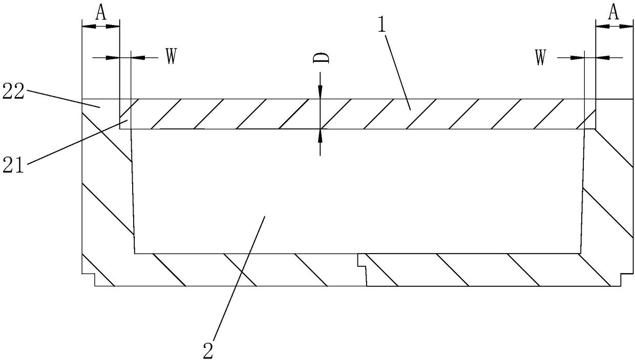
[0029] like figure 1 As shown, the sealed cavity welded joint structure of this embodiment includes a cavity 2 and a cover plate 1, the cover plate 1 is a rectangle, and the cavity 2 is provided with a support step for the cover plate 1 to cover the cavity 2. 21. The outer side of the support step 21 is provided with a step wall 22 that prevents the cover plate 1 from moving horizontally. The thickness of the cover plate 1 is D=6mm. Since D<8mm, the minimum width of the support step 21 is 0.5×6=3mm. The minimum thickness of 22 is 6+1=7mm, that is, W≥3mm, A≥7mm.

Embodiment 2

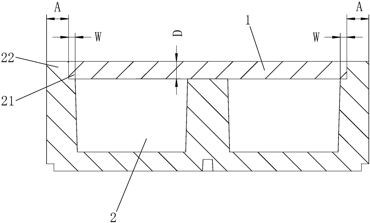
[0031] like figure 2 As shown, the cavity-type water-cooling plate to be welded in this embodiment includes a cavity 2 and a cover plate 1, the cover plate 1 is circular, and the cavity 2 is provided with a support step for the cover plate 1 to cover the cavity 2. 21. The outer side of the support step 21 is provided with a step wall 22 that prevents the cover plate 1 from moving horizontally. The thickness of the cover plate 1 is D=10mm. Since D>8mm, the minimum width of the support step 21 is 4mm, and the minimum thickness of the step wall 22 is 10mm, that is, W≥4mm, A≥10mm.

[0032] The designed structural dimensions of the above two embodiments can effectively prevent welding defects such as edge collapse and welding seam collapse during the welding process, and improve the welding quality.

[0033] like Figure 4 and Figure 5 As shown, Embodiment 1 adopts a welding fixture to clamp the above-mentioned workpiece for welding, and the welding fixture includes a fixing d...


PUM

PropertyMeasurementUnit
widthaaaaaaaaaa
thicknessaaaaaaaaaa
widthaaaaaaaaaa

Abstract

The invention discloses a sealed-type cavity welding connector structure. The sealed-type cavity welding connector structure comprises a cavity and a cover plate; a supporting step is arranged on thecavity; a step wall is arranged on an outer side of the supporting step; the thickness of the cover plate is D; the width of the supporting step is W; the thickness of the step wall is A; and when D is smaller than or equal to 8 mm, the thickness A of the step wall is smaller than or equal to D plus 1, and the width W of the supporting step is greater than or equal to 0.5 multiplied by D. A welding clamp comprises a fixing device, a clamping device which is matched with the fixing device to clamp two sides of a workpiece and a supporting and positioning device which is used for supporting andpositioning the workpiece; and the supporting and positioning device is arranged between the fixing device and the clamping device. A welding method comprises fixing, clamping, welding and other steps. The welding connector structure, the welding clamp and the welding method have the advantages of being good in welding quality, applicable to batch welding of special materials, capable of effectively preventing welding defects and the like.

Description

technical field [0001] The invention belongs to the technical field of friction stir welding, and in particular relates to a closed cavity welded joint structure, a welding fixture and a welding method. Background technique [0002] Parts of closed cavity structure are widely used in radiators, heat exchangers and other equipment, such as cavity water-cooling panels are widely used in radiators of high current and high power distribution cabinets. The cavity and the cover are often made of different materials. If traditional fusion welding is used to weld them, defects such as pores and large deformation are easy to occur, and the product qualification rate is low. Higher requirements and higher processing costs. Friction stir welding can weld dissimilar materials, with good weld quality, less deformation, no pollution, and insensitivity to ambient temperature and humidity. However, there are some problems and difficulties in welding closed cavity structures using friction ...

Claims


Application Information

Patent Timeline
Patent Type & Authority Applications(China)
IPC IPC(8): B23K37/04B23K20/12B23K33/00
CPCB23K20/126B23K33/004
Inventor 李志明钟南周长兴蒋习均
Owner HUNAN JOINFRONT WELDING TECH
Why Eureka
Try Eureka