
General portable spectrum analysis system

A spectrum analysis and spectrum technology, applied in the field of general-purpose portable spectrum analysis systems, can solve the problems of low detection accuracy of instruments, inability to photograph and record, inconvenient for archiving, analysis experiments and proofs, etc., to achieve stable spectral analysis results and reduce operating current. , the effect of improving accuracy

Pending Publication Date: 2018-06-12
GAOLITONG TECH SHENZHEN CO LTD
View PDF0 Cites 7 Cited by
  • Summary
  • Abstract
  • Description
  • Claims
  • Application Information

AI Technical Summary

Problems solved by technology

[0002] At present, conventional Raman spectrometers do not have a video recording function, so they cannot record the analyzed substances, users, and equipment and instruments used in analysis or experiments, nor can they record the analysis or experiment process, so it is not convenient for archiving, analysis experiments and proof.
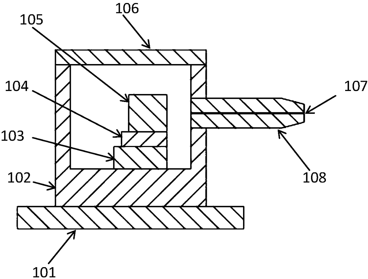
[0003] Moreover, the heat dissipation structure of the laser components in the existing Raman spectrometer such as figure 1 As shown, 101 is the fixed bottom plate of the laser assembly, 102 is the laser shell, 103 is the semiconductor cooling chip (TEC) used for cooling in the laser, 104 is the heat sink for fixing the light-emitting chip in the laser, and 105 is the light-emitting chip in the laser (including collimating mirror and volume grating), 106 is the cover of the laser shell, 107 is the laser output fiber and 108 is the fixed connector of the laser output fiber, such a structure cannot avoid the interference of external heat on the laser, resulting in the thermal stability and power stability of the laser Uncontrollable, resulting in low detection accuracy of the instrument

Method used


Image

  • General portable spectrum analysis system
  • General portable spectrum analysis system
  • General portable spectrum analysis system

Examples


Embodiment Construction

[0047] In order to make the object, technical solution and advantages of the present invention clearer, the present invention will be further described in detail below in conjunction with the accompanying drawings and embodiments. It should be understood that the specific embodiments described here are only used to explain the present invention, not to limit the present invention.

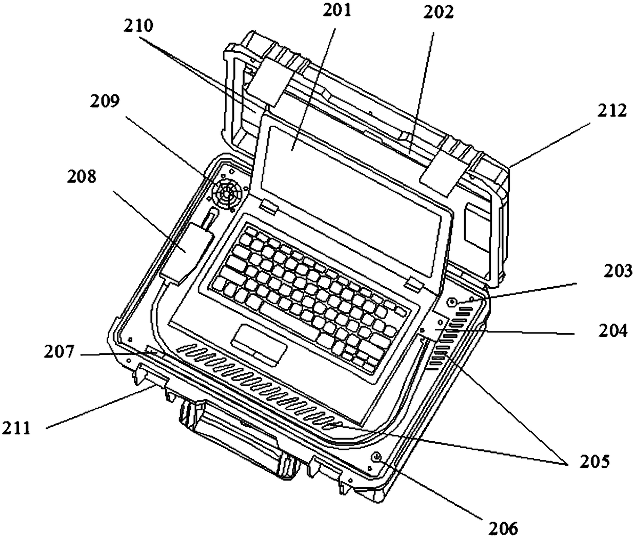
[0048] Such as figure 2 As shown, a general-purpose portable spectral analysis system according to the embodiment of the present invention, 201 is a control display device, 202 is an accessory bag, 203 is an external power plug, 204 is a cover plate for the outlet hole of the optical fiber of the spectral probe and the wire of the camera, and 205 is a ventilation hole 206 is the main switch of the general portable spectrum analysis system, 207 is the camera, 208 is the spectrum probe, 209 is the cooling fan, 210 is the spectrum probe, the spectrum probe optical fiber and the camera wire fixing blo...


PUM


Abstract

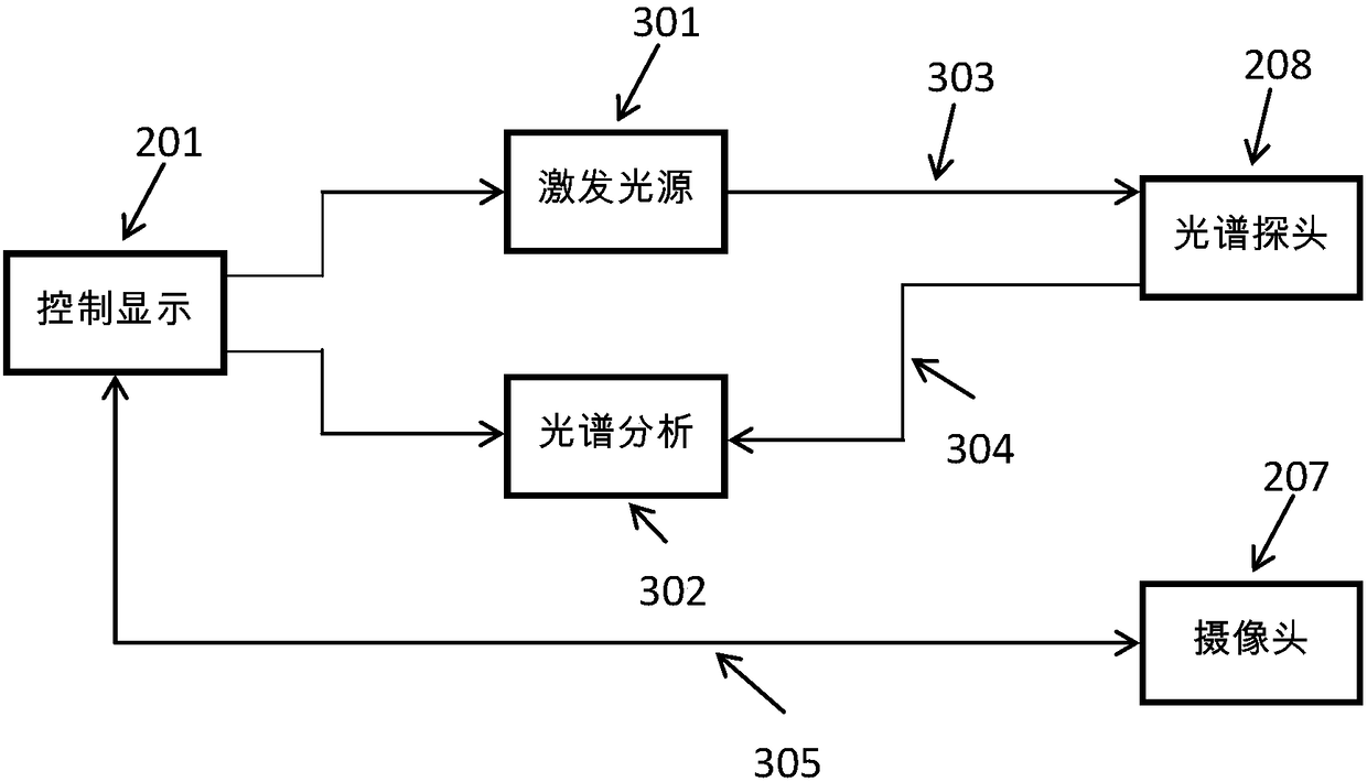
The invention provides a general portable spectrum analysis system. The spectrum analysis system comprises a control display device, an excitation light source module, a spectrum probe, a spectrum analysis module, a camera and a chassis, wherein the control display device is used for controlling the excitation light source module, the spectrum probe, the camera, the spectrum analysis module and adatabase and analyzing and detecting a substance; the excitation light source module is used for outputting exciting light; the spectrum probe is used for emitting the exciting light and receiving a spectrum generated by the interaction of the exciting light and the analyzed substance; the spectrum analysis module is used for analyzing and detecting the spectrum generated by the interaction of theexciting light and the analyzed substance; the camera is used for shooting and recording images of the identified substance, analysis or experimental process, user, equipment and instruments; and thechassis is used for installing the hardware of all the systems, and the like. The general portable spectrum analysis system provided by the invention can be widely applied to various spectral analyses of substances and facilitates recording, filing, experiment analysis, and proofing.

Description

technical field [0001] The invention relates to a general spectrum analysis instrument, in particular to a general portable spectrum analysis system. Background technique [0002] At present, conventional Raman spectrometers do not have a video recording function, so they cannot record the analyzed substances, users, and equipment and instruments used in analysis or experiments, nor can they record the analysis or experiment process, so it is not convenient for archiving, analysis experiments and proof. . [0003] Moreover, the heat dissipation structure of the laser components in the existing Raman spectrometer such as figure 1 As shown, 101 is the fixed bottom plate of the laser assembly, 102 is the laser shell, 103 is the semiconductor cooling chip (TEC) used for cooling in the laser, 104 is the heat sink for fixing the light-emitting chip in the laser, and 105 is the light-emitting chip in the laser (including collimating mirror and volume grating), 106 is the cover of...

Claims


Application Information

Patent Timeline
Patent Type & Authority Applications(China)
IPC IPC(8): G01N21/25G01J3/28G01J3/02
CPCG01J3/02G01J3/28G01N21/25
Inventor 苑高强刘民玉甘新昌
Owner GAOLITONG TECH SHENZHEN CO LTD
Learn More