Device and method used for manufacturing high precision low loss optical fiber Y-branch splitter

A high-precision, low-loss technology, applied in the coupling of optical waveguides, light guides, optics, etc., can solve the problems of optical energy loss, optical energy loss, insufficient coupling of optical fiber links, etc., to achieve high accuracy and the same coupling degree Effect

Active Publication Date: 2018-06-12
JIANGSU STERLITE TONGGUANG FIBER
View PDF11 Cites 0 Cited by
  • Summary
  • Abstract
  • Description
  • Claims
  • Application Information

AI Technical Summary

Problems solved by technology

However, these two types of Y splitters cannot be fully coupled with the existing optical fiber link due to the fact that their materials are different from those of the optical fiber, which increases the connection loss of the system.
Another way to realize the Y splitter using a fiber coupler (for example: 2×2 fiber coupler), taking one end as the output end will cause 3dB loss of optical energy. Researchers have achieved high extinction ratio by various means Both ends of the output, but this requires very high consistency of the two optical fibers, including the coupling length of the two optical fibers, core size, core refractive index, etc., and puts forward very strict requirements on the materials and materials of the optical fiber.
[0004] Chinese patent CN103278885A discloses a manufacturing method of a small-sized optical fiber coupler, including the steps of removing the coating, corroding the cladding, melting the taper, primary encapsulation, and secondary encapsulation; The cladding diameter of the line to be coupled area, although this method shortens the distance between the fiber cores, but by corroding the cladding, it is easy to damage the cladding, resulting in serious loss of optical energy
[0005] Chinese patent CN201903668U discloses a new type of adjustable integrated optical power splitter, which includes a Y-branch waveguide and a coupling area, and an additional waveguide I and an additional waveguide II are arranged in the coupling area, and the additional waveguide I and the additional waveguide II are connected with the coupling The regions are parallel and symmetrically distributed on both sides of the Y branch waveguide. The coupling region is set at the end of the total branch waveguide of the Y branch waveguide. Although the device adds parallel waveguides in the coupling region in order to change the local equivalent refractive index, the device overall Lost energy is still up to 10%

Method used


Image

  • Device and method used for manufacturing high precision low loss optical fiber Y-branch splitter
  • Device and method used for manufacturing high precision low loss optical fiber Y-branch splitter
  • Device and method used for manufacturing high precision low loss optical fiber Y-branch splitter

Examples


Embodiment 1

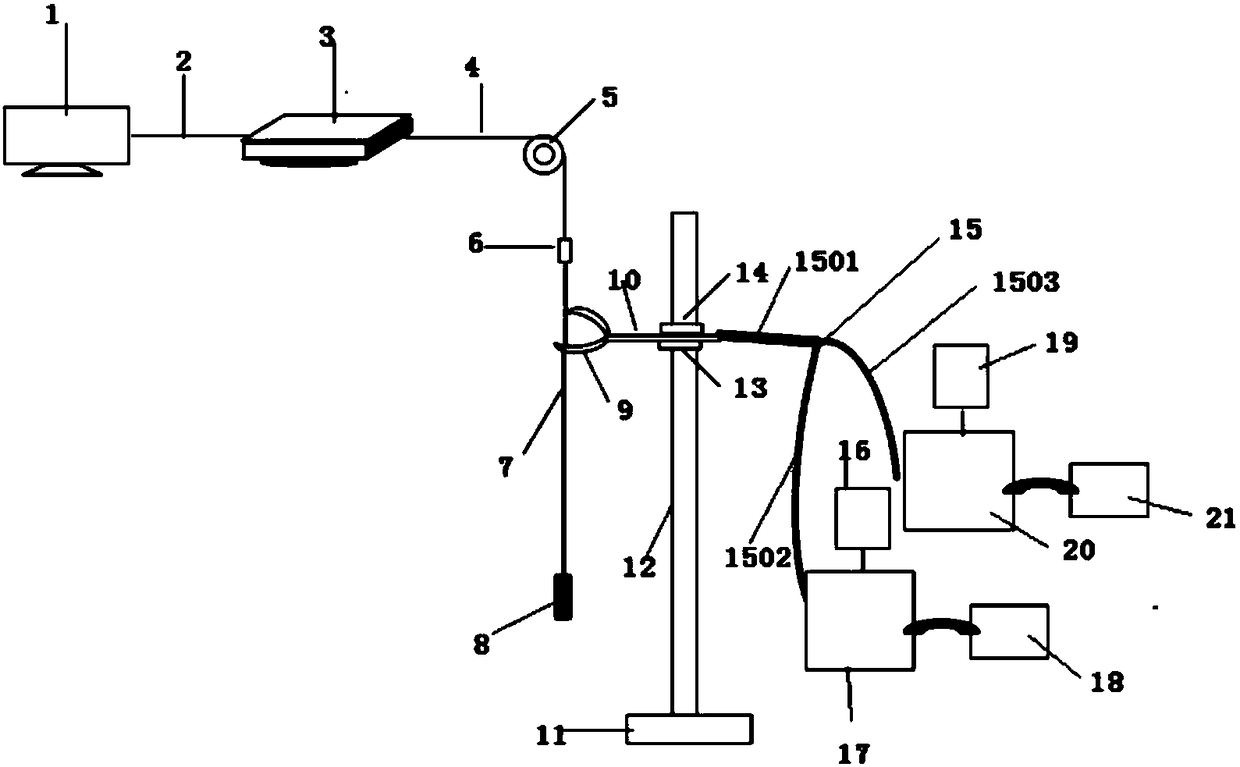
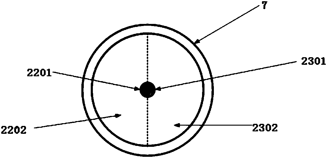
[0041] Such as figure 1 A device and method for making a high-precision and low-loss optical fiber Y splitter shown in the device is characterized in that it includes a computer 1, a data connection line 2, a program-controlled high-precision Mobile platform 3, high-strength connecting wire 4, pulley 5, fixed shelf 6, quartz capillary 7, weight clamp 8, combustion nozzle 9, nozzle pole 10, bracket base 11, bracket rod 12, bracket lower fixture 13, bracket upper Fixture 14, Y-shaped rubber tube 15, mass flow controller I16, mass flow meter I17, oxygen tank 18, mass flow controller II19, mass flow meter II20, hydrogen tank 21; the computer 1 and the program-controlled high-precision mobile platform 3 Connected by data connecting line 2; the optical fiber to be fused is placed in the quartz capillary 7, and the program-controlled high-precision mobile platform 3 passes through the high-strength connecting line 4, pulley 5, fixed shelf 6 and the optical fiber to be fused placed in...

Embodiment 2

[0053] Such as figure 1 A device and method for making a high-precision and low-loss optical fiber Y splitter shown in the device is characterized in that it includes a computer 1, a data connection line 2, a program-controlled high-precision Mobile platform 3, high-strength connecting wire 4, pulley 5, fixed shelf 6, quartz capillary 7, weight clamp 8, combustion nozzle 9, nozzle pole 10, bracket base 11, bracket rod 12, bracket lower fixture 13, bracket upper Fixture 14, Y-shaped rubber tube 15, mass flow controller I16, mass flow meter I17, oxygen tank 18, mass flow controller II19, mass flow meter II20, hydrogen tank 21; the computer 1 and the program-controlled high-precision mobile platform 3 Connected by data connecting line 2; the optical fiber to be fused is placed in the quartz capillary 7, and the program-controlled high-precision mobile platform 3 passes through the high-strength connecting line 4, pulley 5, fixed shelf 6 and the optical fiber to be fused placed in...


PUM


Abstract

The invention relates to a device and method used for manufacturing a high precision low loss optical fiber Y-branch splitter. The device is characterized by comprising a computer, a data connecting line, a program control high precision movable platform, a high strength connecting line, a pulley, a fixing frame, a quartz capillary tube, a heavy object clamp, a combustion nozzle, a nozzle supporting rod, a support base, a support rod, a support lower clamp, a support upper clamp, a Y-shaped rubber pipe, a first mass flow controller, a first mass flowmeter, an oxygen tank, a second mass flow controller, a second mass flowmeter and a hydrogen tank, the computer is connected with the program control high precision movable platform through the data connecting line, an optical fiber to be fusedis placed in the quartz capillary tube, and the program control high precision movable platform is connected with one end of the optical fiber to be fused placed in the quartz capillary pipe throughthe high strength connecting line, the pulley and the fixing frame in sequence. Fusing conditions of different optical fibers can be satisfied, Y-branch splitters with different coupling degrees can be manufactured, and the practicality difficulty is small.

Description

technical field [0001] The invention belongs to the technical field of optical fiber communication systems, and in particular relates to a device and method for manufacturing a high-precision and low-loss optical fiber Y splitter. Background technique [0002] With the advent of the "information age" and the rapid development of communication networks, optical fibers that can meet the needs of large-capacity and high-speed transmission have become a research hotspot. At the same time, high-performance optical devices made of optical fibers are attracting more and more attention. Among them, the Y splitter is an important device unit in the optical fiber communication system. It is not only the basis of optical devices such as beam splitters, multiplexers, optical modulators, M-Z interferometers, and optical switches, but can also be used alone as a power distribution or combiner, mode converter, and mode splitter, and can also be integrated with other components such as las...

Claims


Application Information

Patent Timeline
Patent Type & Authority Applications(China)
IPC IPC(8): G02B6/255
CPCG02B6/2553G02B6/2555
Inventor 孙建彬裴丽维捷卡彬解宇恒邱文强张荣旺
Owner JIANGSU STERLITE TONGGUANG FIBER
Why Eureka
Try Eureka