[0054] The present invention will be further described in detail below in conjunction with the drawings.
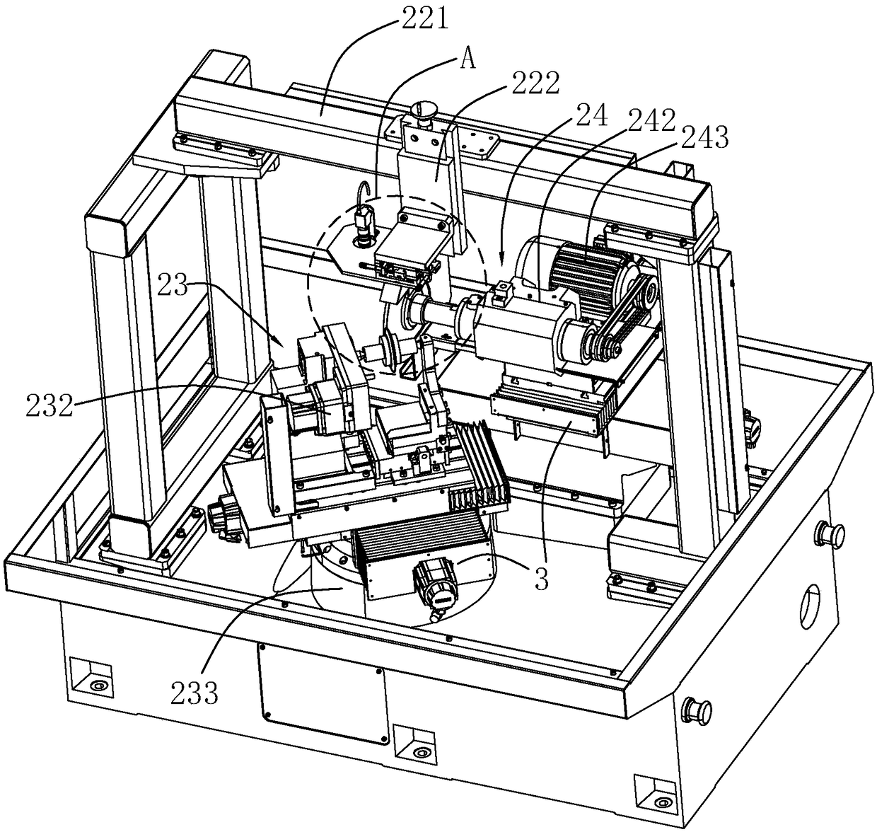
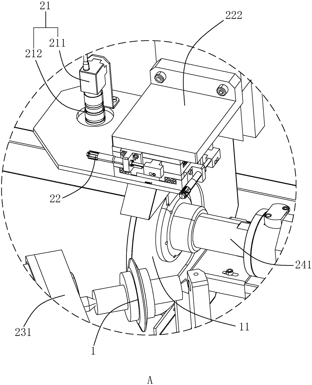
[0055] The invention discloses a digital detection system based on a diamond roller dressing grinder, such as figure 1 with figure 2 As shown, the worktable of the dressing grinder is equipped with a diamond roller 1 and a grinding wheel 11 respectively. According to the technical requirements of the parts to be processed, the diamond roller 1 conforming to the contour shape, size and accuracy is manufactured accordingly. The diamond roller 1 is installed on the dressing grinder. The dressing device is used to dress ordinary ceramic grinding wheels or CBN grinding wheels, and the parts are ground after the grinding wheel 11 is formed. That is, before grinding, the worktable of the dressing grinder is equipped with coordinate subsystem 3 based on X-axis and Y-axis adjustment. The coordinate subsystem 3 is matched with the basic parameters of the diamond roller 1 to make the grinding wheel 11 have a certain geometric shape (training), and then Make the grinding wheel 11 sharp and have a certain roughness (sharpening). Different from the grinding wheel training data, the grinding wheel grinding data depends on the ratio of the grinding speed to the tangential feed rate, which includes one or more of contact conditions, removal amount, removal rate, workpiece material, grinding wheel characteristics and grinding fluid Therefore, it is not convenient to grasp the timing of grinding wheel dressing. Therefore, the digital monitoring system is equipped with a control subsystem for real-time monitoring and timely correction to output the grinding wheel 11 whose real-time grinding data meets the target grinding data, thereby improving the grinding of the grinding machine. The degree of automation of the cutting process reduces the processing cost and scrap rate.
[0056] Such as figure 2 with image 3 As shown, the control subsystem includes at least one set of CCD cameras 21 arranged at the dressing places of the diamond roller 1 and the grinding wheel 11; multiple sets of digital sensors 22 arranged at the dressing places of the diamond roller 1 and the grinding wheel 11; respectively arranged at the diamond roller 1 and the grinding wheel 11 on the first executing part 23 and the second executing part 24; and, communicating with each CCD camera 21 and digital sensor 22, and controlling the actions of the first executing part 23 and the second executing part 24, in order to output in line with the target grinding The data requires the control end 25 of the grinding wheel 11.
[0057] Such as figure 2 As shown, this embodiment of the present invention is a set of CCD cameras 21 located directly above the dressing place of the diamond roller 1 and the grinding wheel 11, which are used to detect the real-time grinding data of the grinding wheel 11, and can be captured once every 0.05s. The overall surface roughness of the grinding wheel 11 is compared with human eyes observation with an optical microscope, which greatly reduces labor costs. At the same time, a protective cover 211 is provided on the outside of the CCD camera 21 to prevent the CCD camera 21 from being affected by trimming and grinding debris, which improves the service life of the CCD camera 21, and the upper side of the CCD camera 21 is provided with a controllable CCD camera 21 for shooting. The far and near adjustment rod 212 can avoid the error caused by missing the shooting distance being too far or too close.
[0058] Such as figure 1 with figure 2 As shown, in this embodiment of the present invention, there are three sets of digital sensors 22 located on the side of the CCD camera 21. The three sets of digital sensors 22 are used to monitor the residual stress, passivation, and heat of the grinding wheel 11 and the diamond roller 1 respectively. degree of damage. At the same time, the beam of the dressing grinder is provided with a guide rail 221, and a sliding member 222 that can be displaced in the vertical direction is provided on the guide rail 221. The digital sensor 22 and the CCD camera 21 are mounted on the sliding member 222 together with the diamond roller 1. Make fine adjustments with the dressing part of the grinding wheel 11 and always keep it directly above the dressing part to ensure the accuracy of monitoring.
[0059] Because the grinding wheel sharpening data has a target correlation with at least one of the surface residual stress, passivation degree, thermal damage degree, and surface roughness of the at least one grinding wheel 11 and the diamond roller 1, the control of the first actuator 23 and the second actuator 24 actions to realize automatic trimming, such as figure 1 with figure 2 As shown, the first actuator 23 includes a double-center supporting fixture 231 arranged on the diamond roller 1, so that the diamond roller 1 can rotate along the axis to dress the grinding wheel 11, and the double-center supporting fixture 231 is provided on one side connected to the diamond roller 1. The first servo motor 232 is driven by a belt pulley to control the work of the diamond roller 1, that is, the power of the first servo motor 232 is used to control the optical repair speed of the diamond roller 1. At the same time, the diamond roller dressing grinder is equipped with a high-precision horizontal turntable 233 that carries the above-mentioned double-center supporting fixture 231, the first servo motor 232 and the diamond roller 1, which is used to realize rotation and index positioning to regulate the feed of the diamond roller 1. rate.
[0060] In order to cooperate with the first actuator 23, such as figure 1 with figure 2 As shown, the second actuator 24 includes a power shaft 241 arranged on the grinding wheel 11, so that the grinding wheel 11 can rotate along the axis to maintain relative movement with the diamond roller 1, and the power shaft 241 is provided with a telescopic cylinder 242 on the side of the grinding wheel 11. To cooperate with the high-precision horizontal turntable 233 to adjust the spacing, so as to achieve precise control of the feed rate. At the same time, the telescopic cylinder 242 is provided with a second servo motor 243 connected to the grinding wheel 11 on the side opposite to the grinding wheel 11, and the grinding wheel 11 is controlled by the belt pulley drive, that is, the power of the second servo motor 243 is used to adjust the polishing speed of the grinding wheel 11 to Determine the ratio of the relative grinding speed to the tangential feed speed, and then obtain the grinding wheel 11 that meets the target grinding data according to the macro-monitoring and micro-control.
[0061] Such as image 3 As shown, the control terminal 25 is connected to the corresponding CCD camera 21, the digital sensor 22, the first actuator 23, and the second actuator 24. The control terminal 25 includes: at least one personal computer 251 and at least one corresponding to the personal computer 251 A programmable logic controller 252, each CCD camera 21 and digital sensor 22 are respectively connected to a personal computer 251 and a programmable logic controller 252, and each first actuator 23 and second actuator 24 are connected to a programmable logic controller 252 . The programmable logic controller 252 includes a database 253, the personal computer 251 has a visual operation interface, and the personal computer 251 is in communication with the programmable logic controller 252, so that the operator can control the programmable logic controller 252 through the personal computer 251 At the same time, the data synchronization between the personal computer 251 and the programmable logic controller 252 is realized. However, in this embodiment of the present invention, the database 253 of the programmable logic controller 252 has a small amount of stored data and uses The stacking algorithm temporarily stores data, while the personal computer 251 uses hard disk storage, which has a large amount of stored data. The programmable logic controller 252 will synchronize to the personal computer 251 for storage after receiving the new preset information to prevent data loss. It realizes the repeated coverage of data, that is, if the latest data comes with new data, it will overwrite and replace the old data to achieve data iteration.
[0062] Such as image 3 As shown, the programmable logic controller 252 further includes a logic control unit 254 and an alarm unit 255. The database 253 and the alarm unit 255 are both connected to the logic control unit 254. Each CCD camera 21 and digital sensor 22 feedback the real-time grinding data of the adjusted grinding wheel 11 to the programmable logic controller 252, and the logic control unit 254 reads from the database 253 according to the feedback information of the CCD camera 21 and digital sensor 22 The grinding data corresponding to the target is sent to the logic control unit 254 for comparison and judgment, and the actions of the first executor 23 and the second executor 24 are controlled by the judgment result.
[0063] Such as image 3 As shown, the database 253 of the programmable logic controller 252 stores the normal working parameters and/or working life information of each component in the digital monitoring system, and it can be judged whether it is necessary according to the normal working parameters and/or working life information of each component If it is replaced or repaired, the alarm unit 255 is controlled to perform a local warning, which realizes the early warning function of the working status of each component, reminds the staff to replace or repair in advance, prevent malfunctions and improve work efficiency.
[0064] In order to improve the stability of the system, such as image 3 As shown, the control terminal 25, the CCD camera 21, and the digital sensor 22 conduct mutual inspections of working status through the interaction of handshake signals. Each time the control terminal 25 starts, a signal is given to the CCD camera 21 and the digital sensor 22. The CCD camera 21 And the digitized sensor 22 feeds back a signal to the control terminal 25. The feedback signal includes the ID information of each CCD camera 21 and the digitized sensor 22. The control terminal 25 compares the feedback signal with the corresponding ID information in the database 253. When there is a problem with the CCD camera 21 or the digital sensor 22, or when a symptom needs to be dealt with but does not affect the normal operation temporarily, and when the change of the sensor is within the error range, an instruction message of refusal to use, warning or normal activation is given.
[0065] To prevent loss of information, such as image 3 As shown, the personal computer 251 and the programmable logic controller 252 perform mutual checks of working status through the interaction of heartbeat signals. That is, if the programmable logic controller 252 and the personal computer 251 cannot receive each other's signal within the preset time, it is determined that the personal computer 251 or the programmable logic controller 252 is down, and the personal computer 251 or the programmable logic controller When one of the devices 252 is down, the system stops running and waits for the personal computer 251 or programmable logic controller 252 in the down state to restart, or the system continues to run, but the data is directly stored in the normal working personal computer 251 or can be The logic controller 252 is programmed, and after the down party restarts, the data is transmitted to the down party. Wherein, the preset time for determining whether the personal computer 251 or the programmable logic controller 252 is normal is not more than 1 minute.
[0066] The digital detection system based on the diamond roller dressing grinder disclosed in the present invention observes the overall surface roughness of the grinding wheel 11 through the CCD camera 21, and the digital sensor 22 monitors the residual stress, passivation and thermal damage of the grinding wheel 11 and the diamond roller 1 , And transmit to the control terminal 25, compare with the preset target grinding data stored in the database 253, and control the actions of the first actuator 23 and the second actuator 24 according to the judgment result to determine the relative grinding speed and tangential direction The ratio of the feed speed until the final match between the real-time grinding data and the target grinding data, thereby increasing the degree of automation of the grinding process of the grinder, improving work efficiency and ensuring product qualification rate.
[0067] This specific embodiment is only an explanation of the present invention, and it is not a limitation of the present invention. After reading this specification, those skilled in the art can make modifications to this embodiment without creative contribution as needed, but as long as the rights of the present invention All requirements are protected by patent law.