External thread core pulling mold of injection molded protective cover and mold core thread machining method

An external thread and protective cover technology, applied in the field of plastic molds, can solve the problems of difficulty in ensuring the maximum outer circle coaxiality of products, ununiform starting positions of threads, and limitations of mold water transport design, etc., to save mold space, internal Effects of stress reduction and dimensional stability improvement

Inactive Publication Date: 2018-06-15
安徽宁国中鼎模具制造有限公司
View PDF1 Cites 1 Cited by
  • Summary
  • Abstract
  • Description
  • Claims
  • Application Information

AI Technical Summary

Problems solved by technology

[0002] An injection-molded protective cover is assembled on the KOMO tube of the automobile air-conditioning condenser to play a sealing role. There is high pressure in the tube, so the size requirements for the protective cover are relatively high; the traditional design is processed according to one out of one or at most one out of two, because the product To play the role of sealing and positioning, it is always difficult to guarantee the coaxiality between the outer circle of the thread and the maximum outer circle of the product. The design of the water transportation of the mold is limited, and the thin slices on the row position are often deformed and broken, which cannot reach the state of mass production; the mold structure for forced thread removal Unable to meet the requirements of product use, the threads need to be processed later, which affects the production efficiency and low efficiency; the starting positions of the threads of the two products of one out of two cannot be unified, resulting in inconsistent positions of the two parts after assembly

Method used


Image

  • External thread core pulling mold of injection molded protective cover and mold core thread machining method
  • External thread core pulling mold of injection molded protective cover and mold core thread machining method
  • External thread core pulling mold of injection molded protective cover and mold core thread machining method

Examples


Embodiment Construction

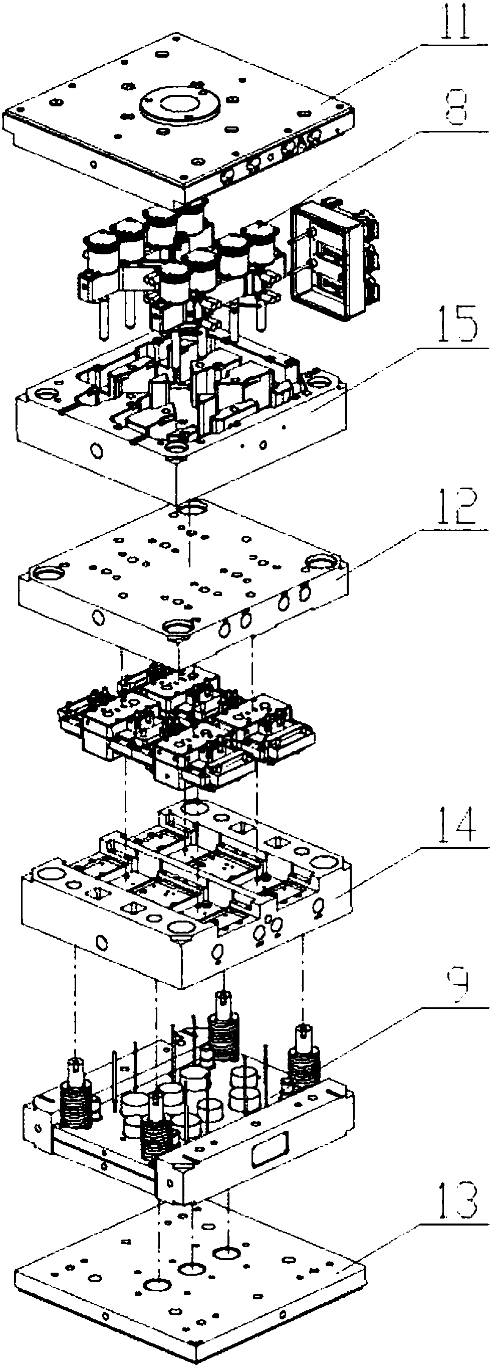
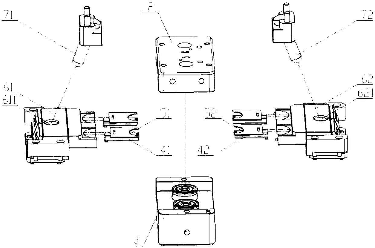
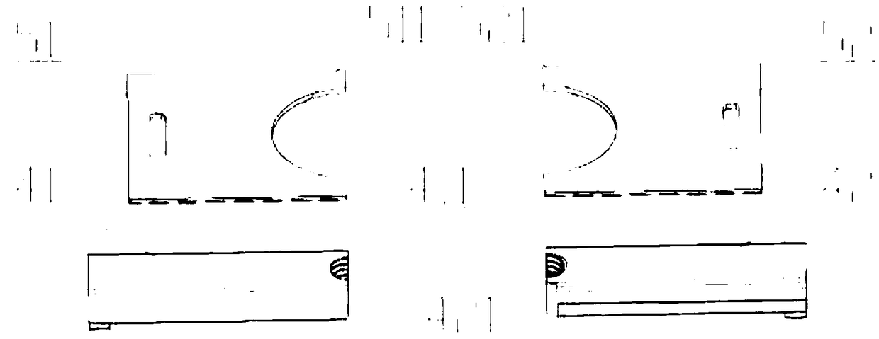
[0022] figure 1 It is an explosion schematic diagram of an external thread core-pulling mold for an injection protective cover proposed by the present invention, figure 2 It is an exploded schematic diagram of the inner mold and side core-pulling mechanism of an external thread core-pulling mold for an injection protective cover proposed by the present invention, image 3 It is a schematic diagram of a mold core of an external thread core-pulling mold for an injection protective cover proposed by the present invention.

[0023] refer to Figure 1-3 , a core-pulling mold for an external thread of an injection protective cover proposed by the present invention, comprising: a fixed mold assembly, a movable mold assembly, an inner mold, a mold core, and a side core-pulling mechanism;

[0024] The fixed mold assembly includes a panel 11, a front template 12 and a heat shield; the heat shield of the front template 12 is respectively installed on both sides of the panel 11, and a ...


PUM


Abstract

The invention discloses an external thread core pulling mold of an injection molded protective cover. The external thread core pulling mold of the injection molded protective cover comprises a fixed mold assembly, a movable mold assembly, inner molds, a mold core and a lateral core pulling mechanism. The mold core comprises a threaded mold core bodies and thin sheet mold core bodies. The threadedmold core bodies extend inwards from the two sides of the inner molds. The thin sheet mold core bodies extend inwards from the two sides of the inner mold bodies. The side core pulling mechanism comprises sliding blocks and inclined guide columns. The inclined guide columns are matched with the sliding blocks in a sliding manner. In the mold opening and closing process, the inclined guide columnsare in linkage with the sliding blocks to move, the sliding blocks drive the mold core to move, and the core pulling action is completed. It is achieved that on the same sliding block mechanism, corepulling of the fine and thin buckle station of the product is achieved, and external thread demolding of the middle column station of the product is also achieved. The invention further provides a thread machining method of the thread mold core. Electrodes are used for machining the threads. The multiple electrodes are turned and milled with one procedure in a unified manner. The datums and initial positions of the rough machining electrodes and the fine machining electrodes are unified, and thread ghosting and dislocation are avoided.

Description

technical field [0001] The invention relates to the technical field of plastic moulds, in particular to an external thread core-pulling mold of an injection protective cover and a thread processing method for the core. Background technique [0002] An injection-molded protective cover is assembled on the KOMO tube of the automobile air-conditioning condenser to play a sealing role. There is high pressure in the tube, so the size requirements for the protective cover are relatively high; the traditional design is processed according to one out of one or at most one out of two, because the product To play the role of sealing and positioning, it is always difficult to guarantee the coaxiality between the outer circle of the thread and the maximum outer circle of the product. The design of the water transportation of the mold is limited, and the thin slices on the row position are often deformed and broken, which cannot reach the state of mass production; the mold structure for f...

Claims


Application Information

Patent Timeline
Patent Type & Authority Applications(China)
IPC IPC(8): B29C45/26B29C45/32B29C45/33B29C45/73B29C45/27B29C33/76B29L1/00B29L31/30B29L31/26
CPCB29C33/76B29C45/2602B29C45/27B29C45/32B29C45/33B29C45/73B29C45/7312B29L2001/00B29L2031/265B29L2031/30
Inventor 韩双能陈增宝任诚芬汪海滨宦昌虎
Owner 安徽宁国中鼎模具制造有限公司
Why Eureka
Try Eureka