Heat supply system

A heating system and heating device technology, applied in heating systems, hot water central heating systems, heating fuels, etc., can solve problems such as unfavorable thermal power unit renovation plans, large renovation scope, and complicated process, and achieve energy improvement Utilization rate, reduction of transformation scope, and reliable performance

Pending Publication Date: 2018-06-15
YANTAI LONGYUAN POWER TECH
View PDF5 Cites 1 Cited by
  • Summary
  • Abstract
  • Description
  • Claims
  • Application Information

AI Technical Summary

Problems solved by technology

[0004] However, in the existing transformation plan, the original steam turbine unit needs to be completely transformed. The transformation scope is large, the process is complicated, the time is long, and the investment is huge, which is not conducive to the advancement of the thermal power unit transformation plan.

Method used


Image

  • Heat supply system
  • Heat supply system
  • Heat supply system

Examples


Embodiment 1

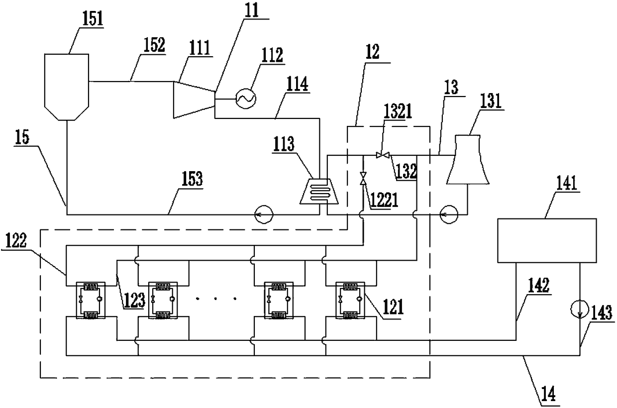
[0020] figure 1 It is the first structural schematic diagram of the heating system in Embodiment 1 of the present invention. Such as figure 1 As shown, the system includes: a steam turbine unit (11), a heat pump device (12), a circulating water device (13) and a heating device (14);

[0021] The steam turbine unit (11) is connected to the circulating water device (13), and the circulating water device (13) absorbs heat from the steam turbine unit (11);

[0022] The heat pump device (12) is connected to the circulating water device (13), and the heat pump device (12) absorbs heat in the circulating water device (13);

[0023] The heat supply device (14) is connected with the heat pump device (12), and the heat pump device (12) transfers the heat absorbed from the circulating water device (13) to the heat supply device (14) for heat supply.

[0024] In the embodiment of the present invention, the steam turbine unit (11) refers to a rotary power machinery unit that converts st...

Embodiment 2

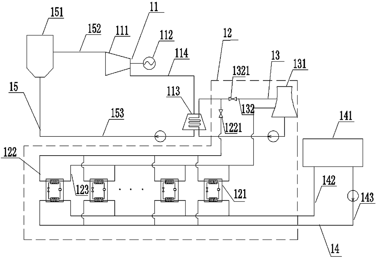
[0060] Figure 5 It is a schematic diagram of the first connection mode of the heat pump device in the heating system in the second embodiment of the present invention. When the heat user needs a higher heating temperature, the connection mode of the heat pump device (12) can be adjusted, such as Figure 5 As shown, multiple heat pumps can also be connected in parallel and then in series. The heating return water with a temperature of T21 from the heating return pipe (143) enters the first group of heat pumps through multiple branch pipes, and the temperature rises to T21' under the action of the first group of heat pumps, and the temperature in each branch pipe is T21' After the heating and returning water are merged, they enter the second group of heat pumps, continue to absorb the heat of the circulating water under the action of the second group of heat pumps and rise to T22, and then merge to the heating water supply pipe (142) for heating.

[0061] Image 6 It is a sc...

Embodiment 3

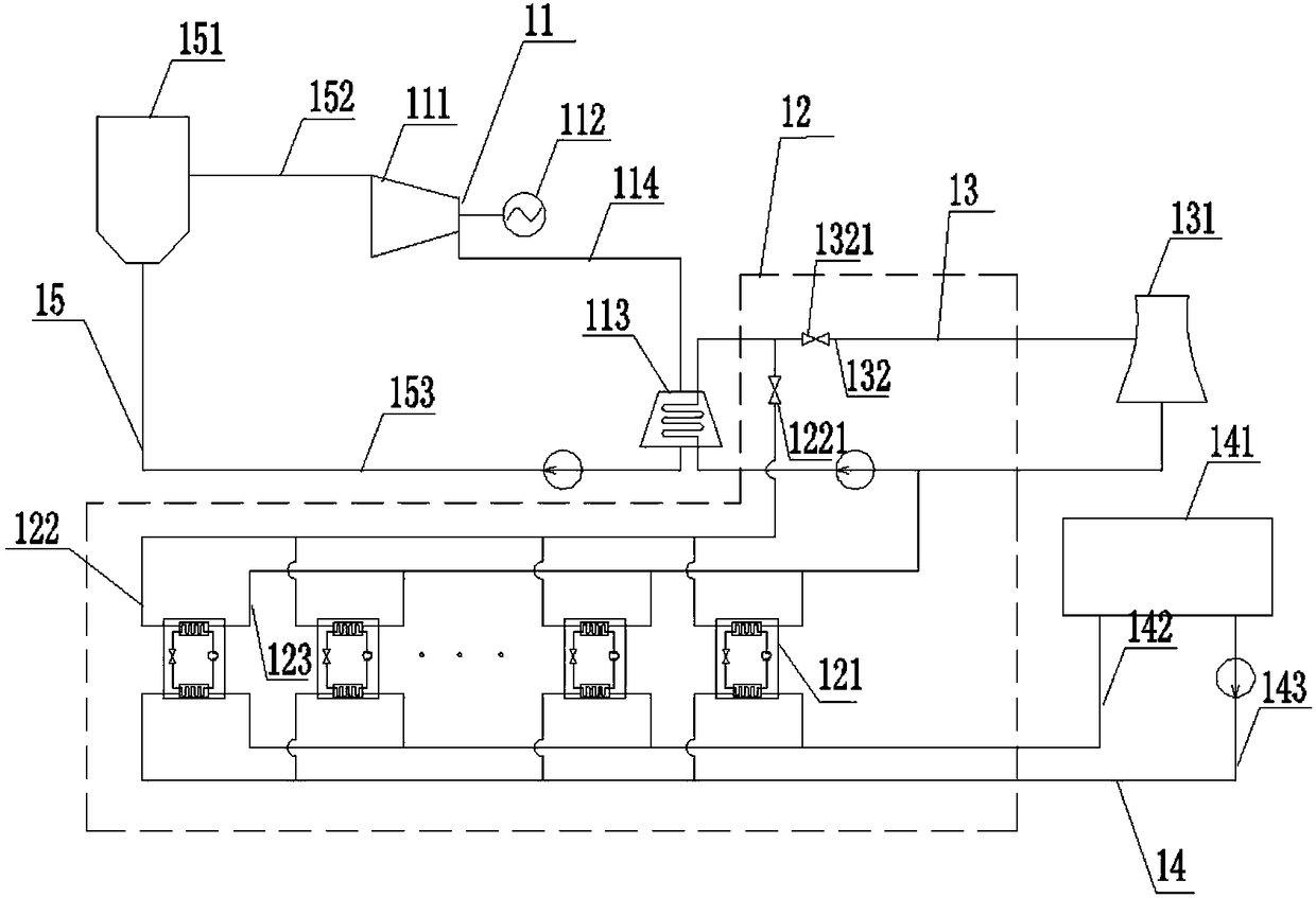
[0067] Figure 7 It is a structural schematic diagram of the heating system in Embodiment 3 of the present invention. Such as Figure 7 As shown, on the basis of the foregoing embodiments, the system also includes: a steam turbine extraction device (16), wherein the steam turbine extraction device (16) includes: a steam turbine extraction pipeline (161), a steam heater drain pipeline (162) and steam heater (163);

[0068] The steam turbine extraction device (16) is connected to the steam turbine unit (11); wherein, the steam turbine extraction device (16) extracts the steam in the steam turbine (111);

[0069] The steam heater (163) is arranged on the heating water supply pipe (142); wherein, the steam heater (163) uses steam to heat the heating water supply to supply heat to the heating equipment (141).

[0070] In the embodiment of the present invention, the steam turbine extraction device (16) refers to a device for extracting part of the steam from the steam turbine (11...


PUM


Abstract

The embodiment of the invention discloses a heat supply system comprising a turbine unit (11), a heat pump device (12), a circulating water device (13) and a heat supply device (14); the turbine unit(11) is connected to the circulating water device (13) used for absorbing heat from the turbine unit (11); the heat pump device (12) is connected to the circulating water device (13), and used for absorbing the heat from the circulating water device (13); the heat supply device (14) is connected to the heat pump device (12) used for absorbing the heat from the circulating water device (13) and transferring the heat to the heat supply device (14) for heat supply. Through increase of the heat pump device between the turbine unit and the circulating water device, the problem that the overall turbine needs to be modified during improvement of the heating capacity of a thermal power unit is solved, and the beneficial effects of simple system structure, rational design and reliable performance are achieved.

Description

technical field [0001] Embodiments of the present invention relate to the technical fields of thermal power generation and energy-saving heating supply, and in particular to a heating system. Background technique [0002] With the adjustment of national energy structure and the increase of residents' demand for heating, it is necessary to carry out technical transformation on the original thermal power units and expand the heating capacity of the original thermal power units. [0003] At present, to expand the heat supply capacity of the original thermal power unit, on the one hand, the traditional pure condensing steam turbine unit that only supplies power but not heat is transformed into a cogeneration unit, and the transformation of the pure condensing steam turbine unit is mainly to transform the original pure condensing It is an extraction steam turbine, so that the steam turbine can extract a part of the steam in the middle stage for heating; or transform the pure cond...

Claims


Application Information

Patent Timeline
Patent Type & Authority Applications(China)
IPC IPC(8): F24D3/10F24D3/18F24D19/00F01D15/10
CPCF01D15/10F24D3/10F24D3/18F24D19/00F24D2220/06F24D2200/123F24D2200/16
Inventor 张勇贾明华潘振艳杨天亮杜永斌付玉玲单国锋邱德来
Owner YANTAI LONGYUAN POWER TECH
Why Eureka
Try Eureka