X-band satellite-borne phased-array antenna

A phased array antenna, X-band technology, applied in antennas, antenna arrays, antenna arrays that are powered independently, etc., can solve the hidden dangers of military satellite data transmission security, shaped reflector antennas have large dimensions, are not easy to miniaturize, Integrated design and other issues to achieve the effect of maximum utilization value, weight reduction and power saving

Inactive Publication Date: 2018-06-15
TIANJIN JINHANG COMP TECH RES INST
View PDF3 Cites 15 Cited by
  • Summary
  • Abstract
  • Description
  • Claims
  • Application Information

AI Technical Summary

Problems solved by technology

The shaped reflector antenna mainly has the following disadvantages: the shape of the shaped reflector antenna is large, and it is not easy to realize miniaturization and integrated design; The security of data transmission brings certain hidden dangers; the shaped reflector antenna beam is wide-angle coverage, and the antenna gain is not high, which has a certain impact on the realization of long-distance data transmission; the shaped reflector antenna has a high profile and is limited in size. Unusable under certain conditions, such as microsatellite platforms
[0004] At present, one of the most widely used spaceborne phased array antennas is circularly polarized waveguide antenna, which realizes ±40° beam scanning characteristics, and the antenna beam is also a spot beam antenna. , High profile, cannot be used under conditions of limited size, such as micro-satellite platforms; and circularly polarized waveguide antennas are mostly made of copper or aluminum, and heavy, which is a limitation for micro-satellite platforms with high load and weight requirements

Method used


Image

  • X-band satellite-borne phased-array antenna
  • X-band satellite-borne phased-array antenna
  • X-band satellite-borne phased-array antenna

Examples


Embodiment 1

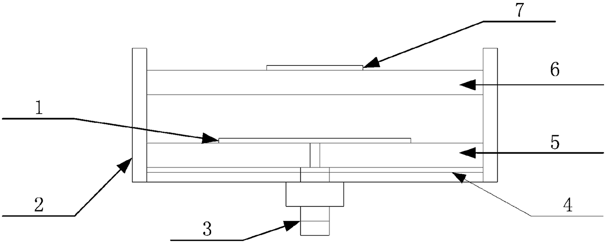
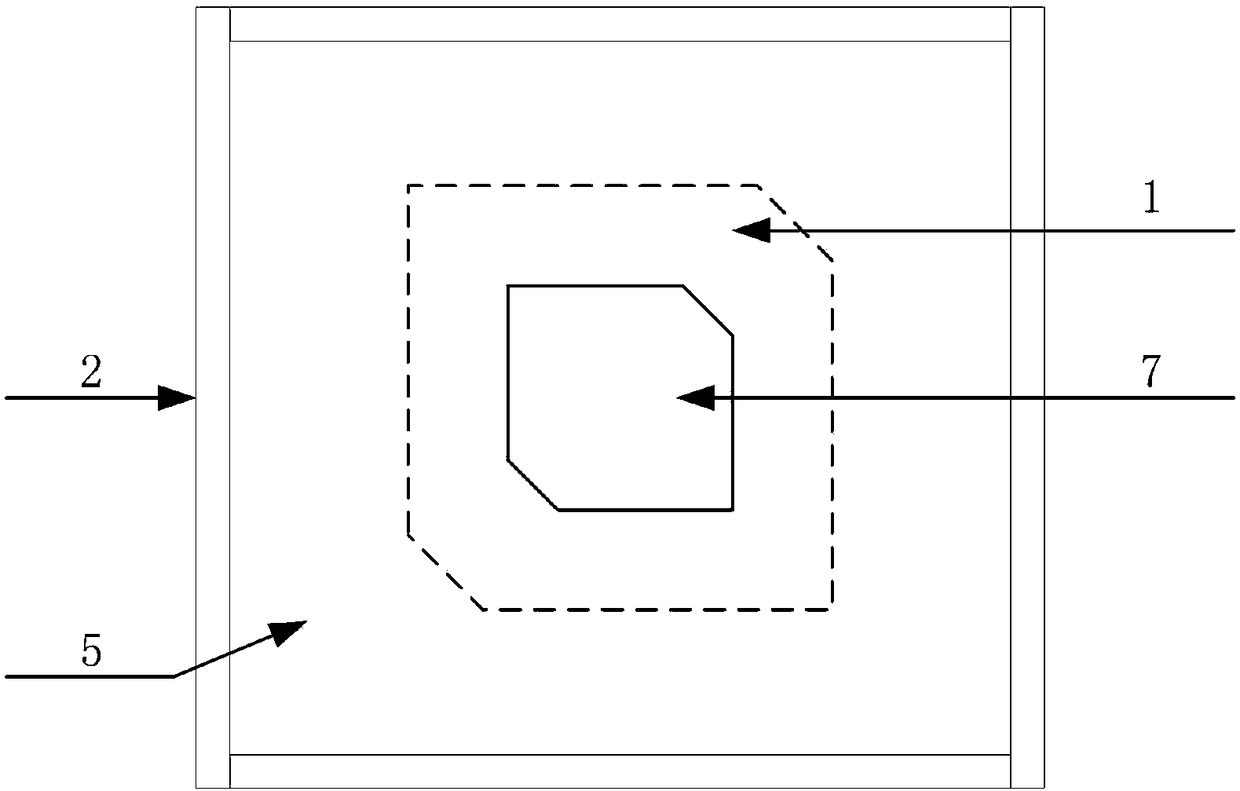
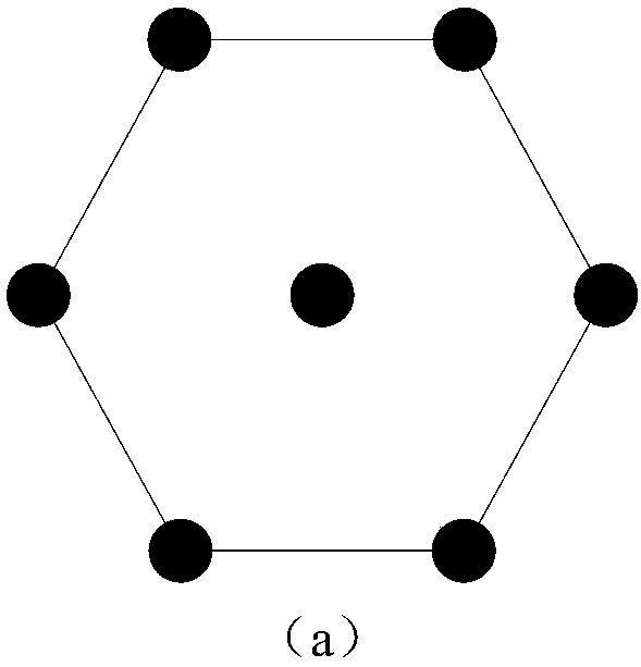
[0032] The X-band spaceborne phased array antenna of this embodiment includes a radome, a mounting plate 9 and a plurality of identical antenna units, the centers of the multiple antenna units are distributed on the mounting plate 9 in an equilateral triangle grid, and the radome 8 covers On a plurality of identical antenna units, and fixed with the mounting plate 9; each antenna unit is a multilayer microstrip antenna, including a radiation patch 1, an antenna unit shell 2, an SMA coaxial connector 3, a ground plate 4, The bottom dielectric board 5, the upper dielectric board 6 and the parasitic patch 7; the inner core of the SMA coaxial connector 3 passes through the mounting board 9, the ground plane 4, and the bottom dielectric board 5 to connect with the radiation patch 1 in turn, and the SMA coaxial The outer skin of the connector 3 is fixedly connected to the mounting plate 9, the mounting plate 9 is connected to the grounding plate 4, the radiation patch 1 is placed on ...


PUM


Abstract

The invention relates to an X-band satellite-borne phased-array antenna. The X-band satellite-borne phased-array antenna comprises an antenna cover, an installation plate and a plurality of same antenna units, wherein centers of the plurality of antenna units are arranged on the installation plate in an equilateral triangle lattice mode, the antenna cover covers the plurality of same antenna unitsand is fixed with the installation plate, each antenna unit is a multi-layer microstrip antenna and comprises a radiation patch, an antenna unit shell, an SMA coaxial connector, a grounding plate, abottom-layer dielectric plate, an upper-layer dielectric plate and a parasitic patch, an inner core of the SMA coaxial connector sequentially penetrates through the installation plate, the grounding plate and the bottom-layer dielectric layer and is connected with the radiation patch, an outer skin of the SMA coaxial connector is fixedly connected with the installation plate, the installation plate is connected with the grounding plate, the radiation patch is arranged on the center of the bottom-layer dielectric plate, the parasitic patch is arranged in the center of an upper surface of the upper-layer dielectric plate, an air medium is arranged between the bottom-layer dielectric plate and the upper-layer dielectric plate, and the peripheries of the bottom-layer dielectric plate, the grounding plate and the upper-layer dielectric plate are fixed with the antenna unit shell.

Description

technical field [0001] The invention belongs to the technical field of microwave antennas, in particular to an X-band space-borne phased array antenna for space-borne data transmission equipment, and its main application direction is high-speed data transmission between satellites in orbit. Background technique [0002] Since the 1960s, satellite communication has developed rapidly and has been widely used in military and civilian applications. With the continuous expansion of satellite business, the number is also increasing, and the data transmission bit rate is also increasing rapidly. To ensure the reliable transmission of information, there are two possible technical approaches: one is to increase the transmission power; the other is to increase the antenna gain. [0003] At present, the commonly used data transmission antennas in the world are mainly "Earth Matching Beam" shaped reflector antennas installed on the ground from satellites, with a diameter of not less th...

Claims


Application Information

Patent Timeline
Patent Type & Authority Applications(China)
IPC IPC(8): H01Q1/36H01Q1/12H01Q1/42H01Q1/50H01Q3/36H01Q21/06
CPCH01Q1/12H01Q1/36H01Q1/42H01Q1/50H01Q3/36H01Q21/065
Inventor 董加伟张涛李鹏钟玲玲
Owner TIANJIN JINHANG COMP TECH RES INST
Why Eureka
Try Eureka