Eureka AIR delivers breakthrough ideas for toughest innovation challenges, trusted by R&D personnel around the world.

3D printing device and printing method for hard alloy part

A cemented carbide, 3D printing technology, applied in the field of laser 3D printing technology, can solve the problems affecting the quality of printed products, scrapping, distortion and deformation of cemented carbide parts, and achieve fully controllable size and morphology, good microstructure, The effect of high printing accuracy

Pending Publication Date: 2018-06-19
GUANGDONG HANBANG 3D TECH CO LTD
View PDF8 Cites 18 Cited by
  • Summary
  • Abstract
  • Description
  • Claims
  • Application Information

AI Technical Summary

Problems solved by technology

However, the current SLM3D printing equipment does not have the functions of double-beam collaborative printing and precision machining, especially the 3D printing of brittle and hard materials will produce serious distortion and deformation, which directly affects the quality of printed products and leads to the scrapping of cemented carbide parts. Limiting the application of 3D printing technology in the field of cemented carbide parts

Method used


Image

  • 3D printing device and printing method for hard alloy part
  • 3D printing device and printing method for hard alloy part
  • 3D printing device and printing method for hard alloy part

Examples


Embodiment Construction

[0086] The following will clearly and completely describe the technical solutions in the embodiments of the present invention with reference to the accompanying drawings in the embodiments of the present invention. Obviously, the described embodiments are only some, not all, embodiments of the present invention. Based on the embodiments of the present invention, all other embodiments obtained by persons of ordinary skill in the art without making creative efforts belong to the protection scope of the present invention.

[0087] It should be noted that when a component is said to be "fixed" to another component, it can be directly on the other component or there can also be an intervening component. When a component is said to be "connected" to another component, it may be directly connected to the other component or there may be intervening components at the same time. When a component is said to be "set on" another component, it may be set directly on the other component or t...


PUM

PropertyMeasurementUnit
diameteraaaaaaaaaa
lengthaaaaaaaaaa
diameteraaaaaaaaaa

Abstract

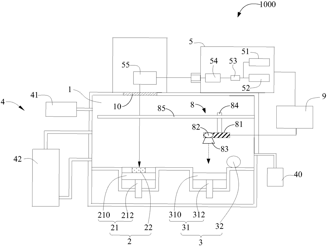
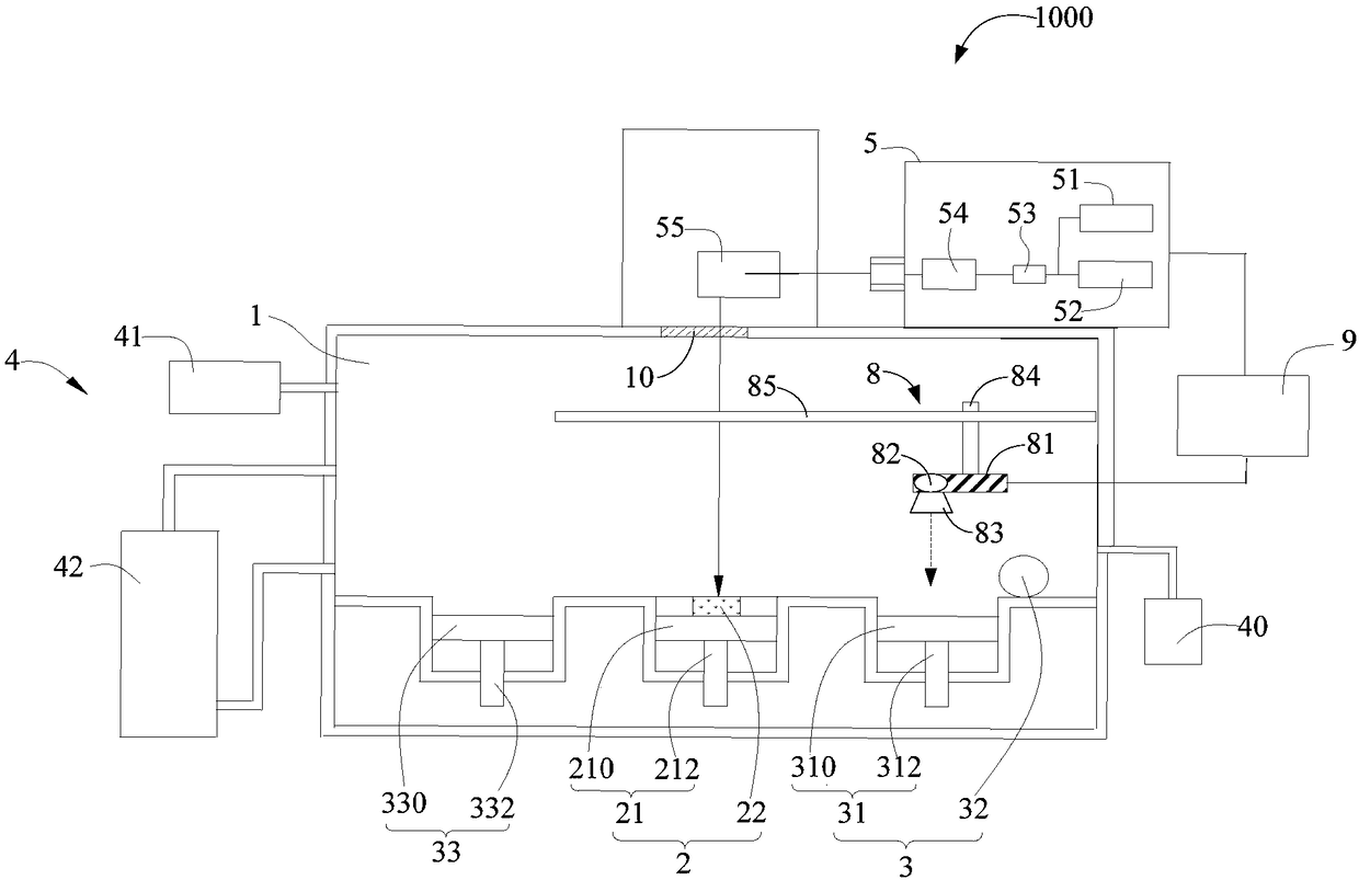
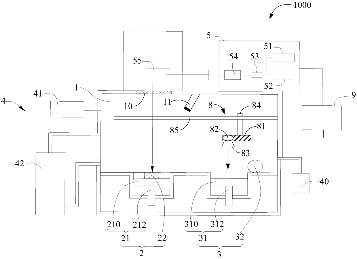
The invention discloses a 3D printing device and printing method for a hard alloy part. The printing device comprises a forming workbench, a powder spreading device, a first laser module, a second laser module and a laser control module, wherein the laser control module is used for controlling a first laser to carry out scanning and forming and outputting pulse laser to carry out precision processing on a printing layer, and used for controlling a second laser to carry out microstructure reduction processing on the printing layer after the printing layer is subjected to precision processing. According to the 3D printing device and printing method for the hard alloy part, the high-stability first laser module is adopted to correspondingly send out continuous laser and the pulse laser, scanning and forming are carried out by the first laser module, furthermore, the pulse laser is used for carrying out precision processing on the printing layer, and the second laser module is used for carrying out microstructure reduction processing, and therefore, two kinds of layered structures with different materials can be printed, the requirement for the complex structure of the composite structure hard alloy part is met, secondary grinding treatment is not need to be carried out on the 3D printing hard alloy part, printing precision is high, size, shape and appearance can be completely controlled.

Description

technical field [0001] The invention relates to a laser 3D printing technology, in particular to a 3D printing device and a printing method for composite structure hard alloy parts. Background technique [0002] Selective Laser Melting (SLM) technology is currently the most precise forming method in metal 3D printing technology. SLM technology uses high-density laser spots to quickly scan two-dimensional graphics in a box with a protective atmosphere. The molten metal powder material is solidified into a thin layer of 20μm-30μm, and the precise hard alloy parts are printed layer by layer. [0003] There are two processing methods for composite structural hard material parts, one is to form parts by powder metallurgy pressing and sintering, and the other is to print parts by 3D printing technology. However, the current SLM3D printing equipment does not have the functions of double-beam collaborative printing and precision machining, especially the 3D printing of brittle and ...

Claims


Application Information

Patent Timeline
Patent Type & Authority Applications(China)
IPC IPC(8): B22F3/105B22F3/24B33Y10/00B33Y30/00
CPCB22F3/003B22F3/24B33Y10/00B33Y30/00B22F2003/248B22F10/00B22F10/38B22F12/49B22F12/70B22F10/366B22F12/44B22F10/28B22F10/36B22F12/20B22F12/47B22F12/90B22F10/32B22F12/43B22F12/13B22F12/55B22F10/50Y02P10/25
Inventor 刘建业戚文军徐卡里牛留辉朱昊威胡高峰高文华关子民黄文欢
Owner GUANGDONG HANBANG 3D TECH CO LTD
Why Eureka
Eureka Blog
Learn More