Planar microstrip duplexer

A duplexer and microstrip technology, applied in the field of radio frequency communication, can solve the problems of large volume, large in-band insertion loss, complex structure, etc., and achieve the effect of reducing volume, reducing insertion loss, and facilitating tuning

Inactive Publication Date: 2018-06-19
NANJING UNIV OF SCI & TECH
View PDF5 Cites 11 Cited by
  • Summary
  • Abstract
  • Description
  • Claims
  • Application Information

AI Technical Summary

Problems solved by technology

[0004] The purpose of the present invention is to provide a planar microstrip duplexer applied to the transceiver system, aiming to solve the

Method used


Image

  • Planar microstrip duplexer
  • Planar microstrip duplexer
  • Planar microstrip duplexer

Examples


Embodiment 1

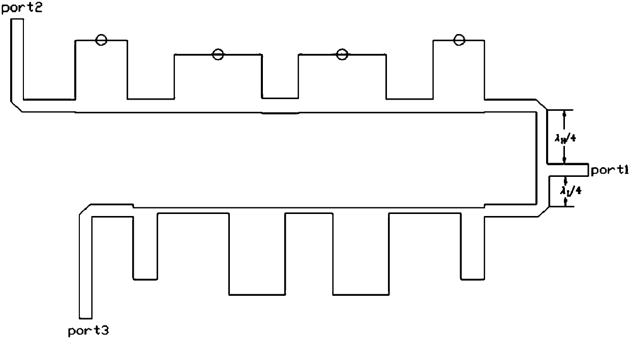
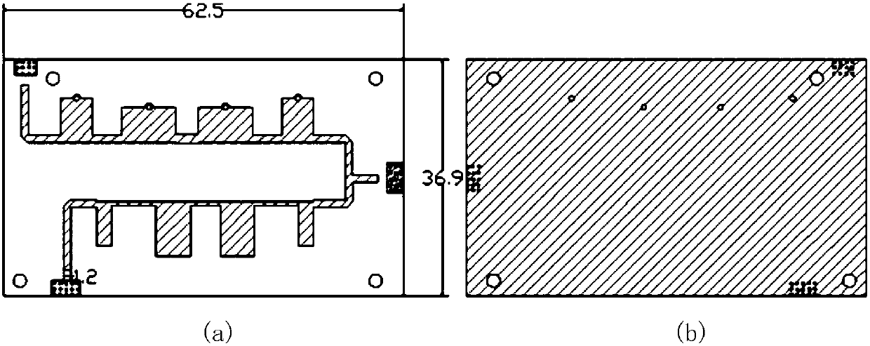
[0023] Such as figure 1 As shown, the planar microstrip duplexer of the present invention includes a microstrip circuit and a double-sided copper-clad dielectric board. The front side of the double-sided copper-clad dielectric board is provided with a microstrip circuit, and the back side is a copper-clad grounding board. The microstrip The circuit includes an input terminal T-joint, a high-pass filter, a low-pass filter and two output ports. The high-pass filter and the low-pass filter are both microstrip stub structures, and one end thereof is transformed by a quarter impedance The lines are connected in parallel to the T-shaped connector at the input end, and the other ends of the high-pass filter and the low-pass filter are respectively connected to an output port.

[0024] Such as figure 2 As shown, the transverse branch of the T-joint at the input end is a 50-ohm open-circuit microstrip line, and the external signal is input through the connector. The two output ports...


PUM

PropertyMeasurementUnit
Thicknessaaaaaaaaaa

Abstract

The invention provides a planar microstrip duplexer. The planar microstrip duplexer comprises a microstrip circuit and a double-surface copper-clad dielectric plate, the front surface of the double-surface copper-clad dielectric plate is provided with the microstrip circuit, the backside of the double-surface copper-clad dielectric plate is provided with a copper-clad grounding plate, the microstrip circuit comprises an input terminal T-type joint, a high-pass filter, a low-pass filter and two output ports, the high-pass filter and the low-pass filter are both microstrip stub structures, one ends the high-pass filter and the low-pass filter are connected to the input terminal T-type joint in parallel through quarter-impedance conversion lines, the other ends of the high-pass filter and thelow-pass filter are respectively connected to one output port, and each stub of the high-pass filter can be used for being connected with the copper-clad grounding plate through grounding holes and becomes a short circuit terminal for introduction of magnetic coupling after connection. The planar microstrip duplexer is advantaged by simple structure, light weight, small size, low in-band insertion loss, convenient tuning, and low production and manufacturing costs.

Description

technical field [0001] The invention relates to the technical field of radio frequency communication, in particular to a planar microstrip duplexer. Background technique [0002] A duplexer is an essential device for communication system equipment. With the increasing shortage of frequency resources in wireless communication systems, the requirements for performance indicators of duplexers are also getting higher and higher. Reducing the size and cost of the duplexer is very important for reducing the cost of the entire communication system. A new duplexer with high selectivity, high isolation, miniaturization, and low cost is an urgent demand in the market, and it is also an inevitable trend in the development of duplexers. [0003] At present, duplexers are mainly used in microwave and millimeter wave circuit systems to achieve the purpose of transmitting and receiving duplex channels and frequency band duplex communications. The main design of the duplexer includes the...

Claims


Application Information

Patent Timeline
IPC IPC(8): H01P1/20H01P1/203
CPCH01P1/20H01P1/203
Inventor 张静静杨亚南孙琳琳
Owner NANJING UNIV OF SCI & TECH
Why Eureka
Try Eureka