Inverter protection circuit and protection method and device

A technology for protecting circuits and converters, applied to output power conversion devices, AC power input conversion to DC power output, electrical components, etc., can solve problems such as voltage source converter overvoltage, overcurrent, etc., to achieve The effect of a failover restart

Pending Publication Date: 2018-06-22
NR ELECTRIC CO LTD +1
View PDF0 Cites 28 Cited by
  • Summary
  • Abstract
  • Description
  • Claims
  • Application Information

AI Technical Summary

Problems solved by technology

The above solution will still cause serious overvoltage and overcurrent in the voltage source converter if extreme faults occur in the DC tra

Method used


Image

  • Inverter protection circuit and protection method and device
  • Inverter protection circuit and protection method and device
  • Inverter protection circuit and protection method and device

Examples


Embodiment Construction

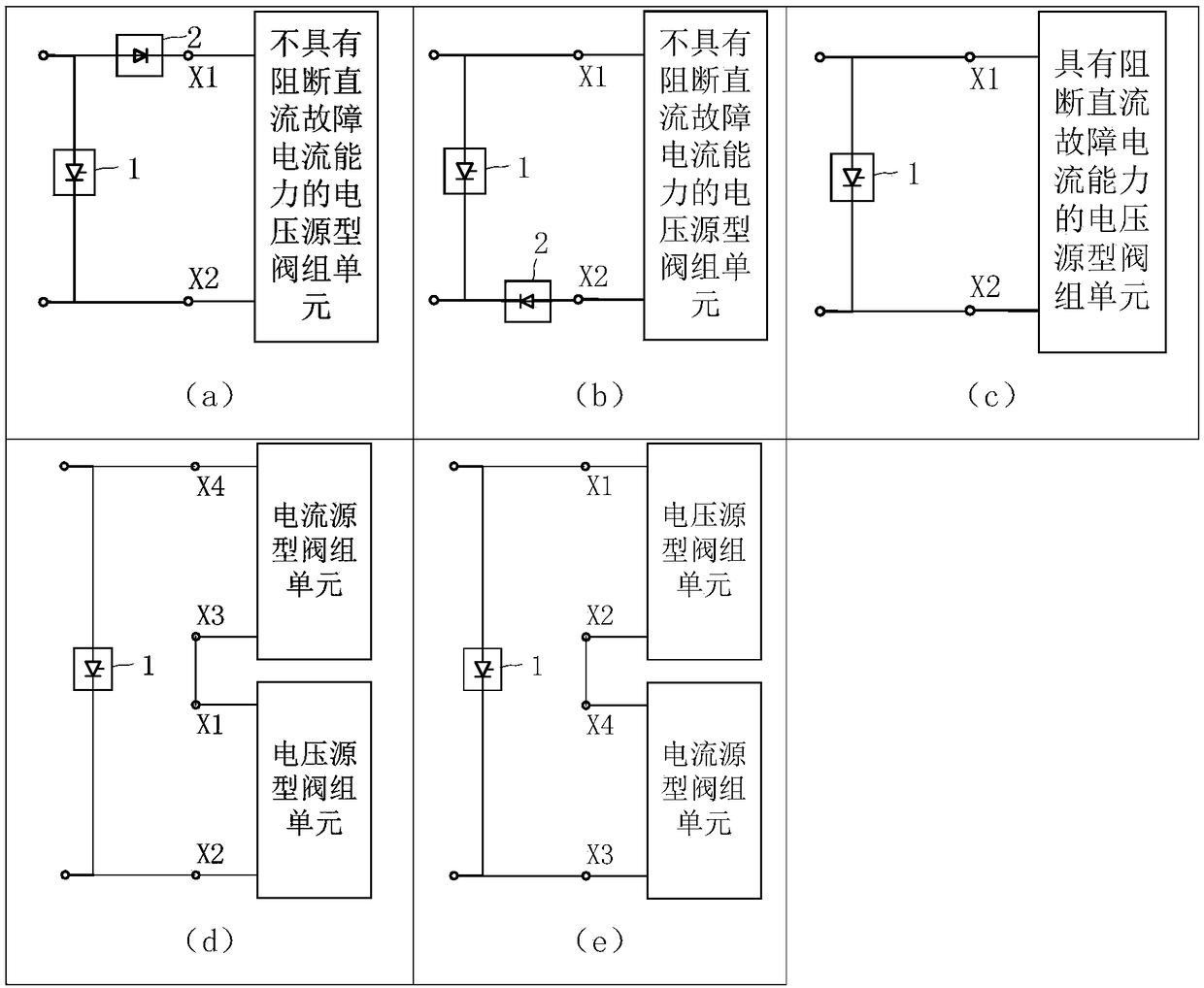
[0046] The embodiments of the present invention will be described with the aid of the following drawings, in which the same components use the same reference numerals. figure 1 A converter protection circuit proposed for the present invention is used to protect a converter with DC fault ride-through capability. It includes at least one bypass thyristor valve group 1, and the connection method is between two converters with DC fault ride-through capability. The bypass thyristor valve group 1 is connected in parallel with the bypass thyristor valve group 1. The anode of the bypass thyristor valve group 1 is connected to the positive pole of the inverter with DC fault ride-through capability, and the cathode of the bypass thyristor valve group 1 is connected to the inverter with DC fault ride-through capability. The negative pole is connected.

[0047] figure 1 (a) and figure 1 (b) is the series connection topology of the diode valve group 2 and the voltage source valve group unit wi...


PUM


Abstract

The invention discloses an inverter protection circuit. The circuit is used for protecting a voltage source inverter in an inverter with direct current fault ride-through capability, wherein the inverter is composed of a diode valve group or a current source type valve group unit and a voltage source type valve group unit, and the diode valve group or the current source type valve group unit and the voltage source type valve group unit are connected in series. A bypass thyristor valve group is connected in parallel with both ends of the inverter with direct current fault ride-through capability. The anode and the cathode of the bypass thyristor valve group are connected with the positive pole and the negative pole of the inverter with direct current fault ride-through capability respectively. The invention further discloses an inverter protection method. When the voltage source inverter detects that an alternating current or direct current system is failed and the voltage or current ofthe voltage source inverter exceeds a threshold value, the bypass thyristor valve group is input, and fault information is transmitted to a rectifier station. The rectifier station reduces the directcurrent voltage and reduces the direct current to zero. The bypass thyristor valve group is turned off due to current zero-crossing. The voltage source inverter protection circuit effectively solvesovervoltage and overcurrent problems caused by direct current charging of the voltage source inverter, and ensures the reliable operation of the voltage source inverter.

Description

Technical field [0001] The invention belongs to the fields of flexible direct current transmission and high voltage direct current transmission, and specifically relates to a converter protection circuit, a protection method and a device. Background technique [0002] The advantage of current source HVDC transmission based on thyristor is that the loss of the converter is small, and the DC system can be restarted by phase shifting when a DC line failure occurs; the disadvantage is that the inverter side converter works in an active inverter and cannot be connected Source system; commutation failure is likely to occur when the inverter side is connected to the weak AC system with disturbance; the reactive power consumption is large, the voltage and current harmonic content is high, and the filter device needs to be installed to provide reactive power and filtering. The advantages of DC transmission based on voltage source converters are high controllability and can be connected to...

Claims


Application Information

Patent Timeline
IPC IPC(8): H02M1/32H02J3/36
CPCH02J3/36H02M1/32Y02E60/60H02M7/483H02M1/325H02M7/4835
Inventor 卢东斌李海英曹冬明
Owner NR ELECTRIC CO LTD
Why Eureka
Try Eureka