Supercharge Your Innovation With Domain-Expert AI Agents!

Capacitance lowering circuits and modularized multi-level current converter

A converter and circuit technology, which is applied in the direction of high-efficiency power electronic conversion, conversion of AC power input to DC power output, electrical components, etc., can solve the problems of small adjustment range, low accuracy and poor effect, and achieve a large adjustment range. , the effect of reducing the capacitance value and reducing the oscillation amplitude

Pending Publication Date: 2018-06-22
CHINA EPRI ELECTRIC POWER ENG CO LTD +4
View PDF0 Cites 0 Cited by
  • Summary
  • Abstract
  • Description
  • Claims
  • Application Information

AI Technical Summary

Problems solved by technology

[0004] In order to overcome the shortcomings of small adjustment range, poor effect and low accuracy in the above-mentioned prior art, the present invention provides a derating circuit and a modular multilevel converter including the derating circuit. The derating circuit includes the bridge arm reactance L1 , bridge arm reactance L2 and switching circuit, bridge arm reactance L1 and bridge arm reactance L2 are connected in series, switching circuit and bridge arm reactance L1 are connected in parallel, switching circuit includes anti-parallel first branch and second branch, the first Both the branch and the second branch include multiple thyristors in series, which reduces the capacitance of the sub-module capacitor on the premise of meeting the design requirements of the fluctuation amplitude of the capacitor voltage of the sub-module, with a large adjustment range and a significant derating effect

Method used


Image

  • Capacitance lowering circuits and modularized multi-level current converter
  • Capacitance lowering circuits and modularized multi-level current converter
  • Capacitance lowering circuits and modularized multi-level current converter

Examples


Embodiment 1

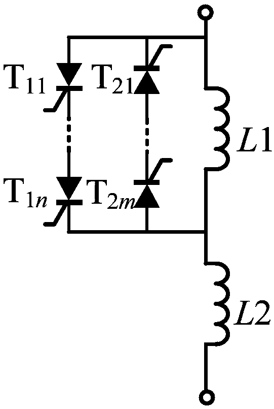
[0037] Embodiment 1 of the present invention provides a derating circuit, the specific structural diagram of the derating circuit is as follows figure 1 as shown, figure 1 middle, T 11 ,...,T 1n and T 21 ,...,T 2m Both are thyristors, n represents the number of thyristors in the first branch, m represents the number of thyristors in the second branch, and the derating circuit includes bridge arm reactance L1, bridge arm reactance L2 and switching circuit;

[0038] The bridge arm reactance L1 is connected in series with the bridge arm reactance L2, and the switching circuit is connected in parallel with the bridge arm reactance L1;

[0039] The above-mentioned switching circuit includes a first branch and a second branch in anti-parallel connection, and both the first branch and the second branch include a plurality of thyristors connected in series. Specifically, all the thyristors in the first branch have the same direction, All the thyristors in the second branch have t...

Embodiment 2

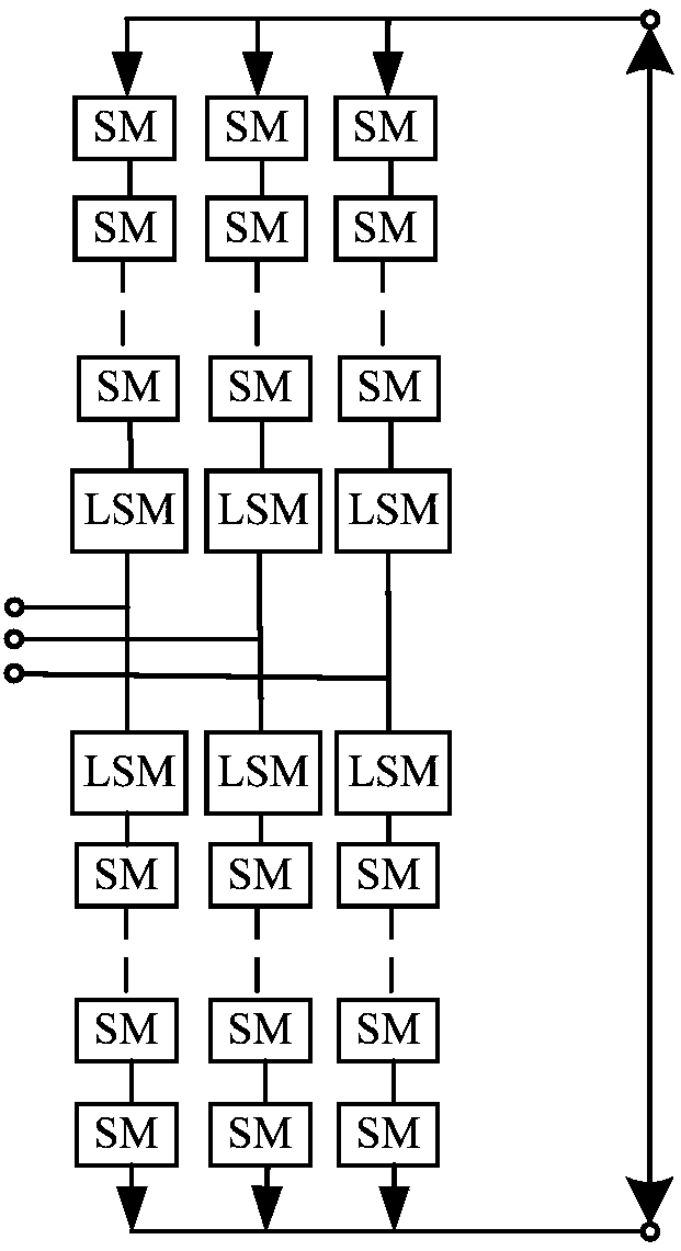
[0052] Embodiment 2 of the present invention provides a modular multilevel converter, the specific structure diagram is as follows figure 2 as shown, figure 2 Among them, SM represents a sub-module, LSM represents a derating circuit, which includes three upper bridge arms and three lower bridge arms, the derating circuit and multiple sub-modules included in both the upper bridge arm and the lower bridge arm; after multiple sub-modules are connected in series , in series with the derating circuit. And the derating circuit is located on the AC side of the upper bridge arm and the lower bridge arm.

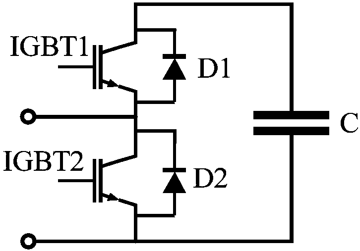
[0053] Such as image 3 As shown, the sub-module is a half-bridge sub-module, which includes a first IGBT module, a second IGBT module and an energy storage capacitor C;

[0054] After the first IGBT module and the second IGBT module are connected in series, they are connected in parallel with the energy storage capacitor C.

[0055] The first IGBT module IGBT and a diode D1 co...


PUM


Abstract

The invention provides capacitance lowering circuits and a modularized multi-level current converter comprising the capacitance lowering circuits. Each capacitance lowering circuit comprises a bridgearm reactor L1, a bridge arm reactor L2 and a switching circuit, each switching circuit comprises a first branch circuit and a second branch circuit which are in reverse parallel connection, the firstbranch circuits and the second branch circuits all comprise multiple thyristors in series connection, each bridge arm of the modularized multi-level current converter comprises the corresponding capacitance lowering circuit and multiple submodules, and after being in series connection, the submodules are in series connection with the capacitance lowering circuits. On the premise of meeting fluctuation amplitude design requirements of capacitor voltages of the submodules, capacitance values of capacitors of the submodules are lowered, the adjusting range is large, the capacitance lowering effect is obvious, by allocating reactance values of the upper bridge arm and the lower bridge arm, original energy distribution of the bridge arms is changed, then the capacitor voltage waveform of eachsubsidiary module in the energy transmitting process is changed, the oscillation amplitude of the capacitor voltages of the submodules when the same active power is transmitted is effectively lowered,and thus the capacitor capacitance values of the submodules in the modularized multi-level current converter are lowered.

Description

technical field [0001] The invention relates to the technical field of direct current transmission, in particular to a capacity reduction circuit and a modular multilevel converter including the capacity reduction circuit. Background technique [0002] The flexible DC transmission technology mainly adopts the voltage source converter. The power electronic devices in this type of converter have the advantages of low inertia, four-quadrant operation, and flexible power flow control. The most commonly used structure of the voltage source converter in the flexible DC transmission technology is the modular multilevel converter. The advantages of the modular multilevel converter include: 1) The modular structure makes the system easy to expand, so as to realize Higher voltage level, easy to build redundant structure also improves the reliability of the system; 2) Low switching frequency, reducing switching loss; 3) Can generate more levels, high waveform quality, no need to instal...

Claims


Application Information

Patent Timeline
IPC IPC(8): H02M7/162H02M7/483H02M7/521
CPCH02M7/1623H02M7/483H02M7/521H02M1/0048Y02B70/10
Inventor 查鲲鹏田蘅栾洪洲李帅陈月卿卢昭禹赵成勇
Owner CHINA EPRI ELECTRIC POWER ENG CO LTD
Features
  • R&D
  • Intellectual Property
  • Life Sciences
  • Materials
  • Tech Scout
  • Unparalleled Data Quality
  • Higher Quality Content
  • 60% Fewer Hallucinations
Learn More