Transfer device of fuel oil

A transfer device and fuel oil technology, which is applied in transportation and packaging, ship parts, ships, etc., can solve the problems of fuel oil transfer efficiency deterioration, transfer efficiency deterioration, cost increase, etc., to prevent transfer efficiency from deterioration, prevent Effect of temperature drop and viscosity increase suppression

Active Publication Date: 2018-06-26
HOKUSHIN ENG
View PDF7 Cites 3 Cited by
  • Summary
  • Abstract
  • Description
  • Claims
  • Application Information

AI Technical Summary

Problems solved by technology

However, the heated fuel oil is prone to convection in the fuel oil storage tank
As a result, the temperature distribution of the fuel in the fuel oil storage tank becomes uneven, and when the temperature of the fuel oil at the extraction position is

Method used


Image

  • Transfer device of fuel oil
  • Transfer device of fuel oil
  • Transfer device of fuel oil

Examples


Example Embodiment

[0023] Hereinafter, specific embodiments of the present invention will be described.

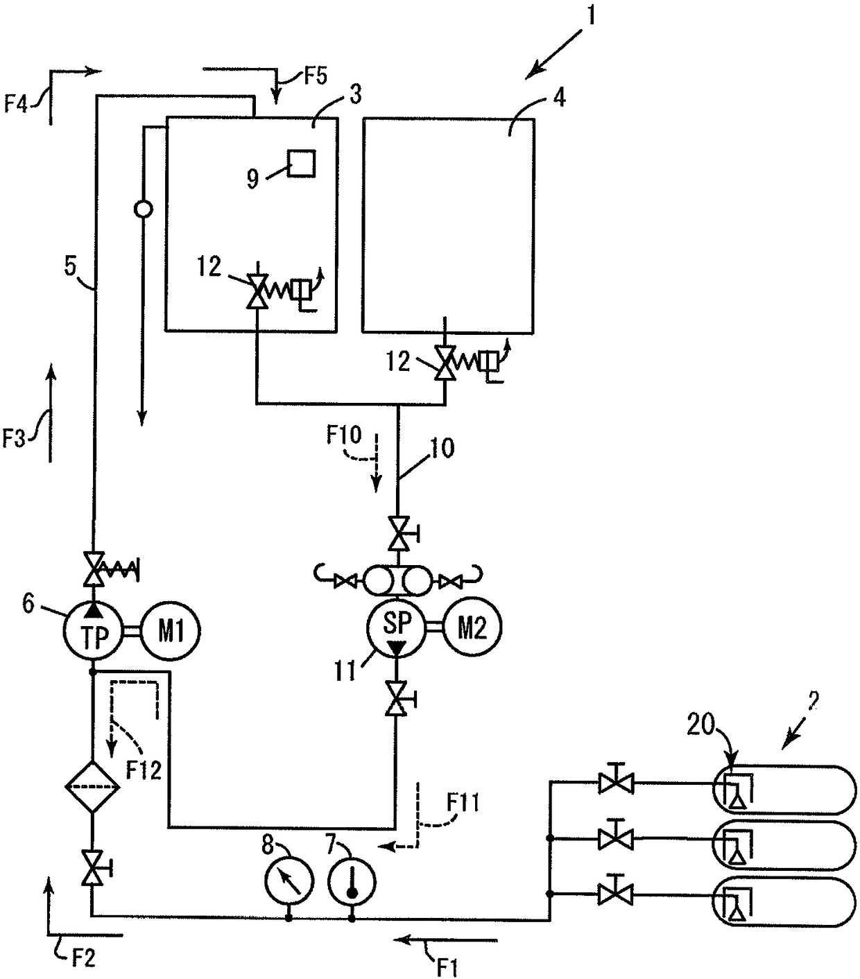
[0024] figure 1 It is a figure which shows the structure of the fuel oil transfer apparatus 1 of the specific embodiment of this invention.

[0025] The fuel oil transfer device 1 includes a fuel oil precipitation tank 3 and a fuel oil daily tank 4 that communicate with a fuel oil storage tank 2.

[0026] The fuel oil precipitation tank 3 is a tank for heating the fuel oil. As an example, the fuel oil is heated to a temperature of 70 to 80° C. by a heater not shown.

[0027] The fuel oil storage tank 2 and the fuel oil precipitation tank 3 are in communication with each other through a transfer pipe 5, and a transfer pump 6, a temperature sensor 7, and a pressure sensor 8 are arranged in the middle.

[0028] The temperature sensor 7 measures, for example, the temperature of the fuel oil inlet side of the transfer pump 6.

[0029] The pressure sensor 8 is provided to monitor the pressure change of the f...


PUM


Abstract

The invention provides a fuel oil transfer device capable of preventing fuel oil taken out from a fuel oil storage tank from being affected by atmospheric temperature and being in a viscosity increasing state, to prevent deterioration of transfer efficiency. The fuel oil transfer device comprises: a fuel oil storage tank (2) arranged on a position to receive heat of atmosphere; a fuel oil precipitation tank (3) for heating the fuel oil sucked from the fuel oil storage tank (2), and a fuel oil daily tank (4) for temporarily storing the heated fuel oil in the fuel oil storage tank (2) so that heated fuel oil return to the fuel oil storage tank (2) and the fuel oil can be circulated. The fuel oil storage tank (2) has a suction pipe (2C) having a bell mouth (2B) opening toward the bottom in the deepest position in a longitudinal direction; and a steam heating pipe (30) disposed in pairs near the bell mouth (2B).

Description

technical field [0001] The present invention relates to a fuel oil transfer device, and more specifically, to a fuel oil storage tank for storing fuel oil supplied to an internal combustion engine or the like. Background technique [0002] Fuel oil used in boilers such as ships and generators is stored in storage units such as tanks, and is supplied to internal combustion engines and the like for consumption. [0003] As a storage unit for fuel oil used in ships, for example, in the case of a cargo ship, tanks arranged on a part of the double bottom provided on the lower side of the cargo hold are used. [0004] However, at this position, if a part of the double bottom is damaged due to grounding or the like, fuel oil may flow out from the fuel oil storage part. [0005] Therefore, it is proposed to secure a space for the fuel oil storage tank not at the bottom of the hull, but at a position higher than the bottom such as a corner near the upper deck (for example, Patent Do...

Claims


Application Information

Patent Timeline
IPC IPC(8): B63B11/04
CPCB63B11/04B63J2/14
Inventor 千千波孝泰
Owner HOKUSHIN ENG
Why Eureka
Try Eureka