Pyrolysis and gasification incinerator for garbage and method

A pyrolysis gasification and incinerator technology, applied in the combustion method, incinerator, combustion type, etc., can solve the problems of large equipment area, low combustion efficiency, insufficient combustion, etc., to save area and improve The effect of combustion efficiency and design cost saving

Active Publication Date: 2018-06-26
BEIJING BUILDING MATERIALS ACADEMY OF SCI RES
View PDF4 Cites 4 Cited by
  • Summary
  • Abstract
  • Description
  • Claims
  • Application Information

AI Technical Summary

Problems solved by technology

[0005] The present invention provides a kind of garbage pyrolysis gasification incineration that overcomes the problems of insufficient combustion, low combustion efficiency and large equipment footprint in most of the existing garbage incinerators or at least partially solves the above problems furnace and method

Method used


Image

  • Pyrolysis and gasification incinerator for garbage and method
  • Pyrolysis and gasification incinerator for garbage and method
  • Pyrolysis and gasification incinerator for garbage and method

Examples


Embodiment Construction

[0031] The specific implementation manners of the present invention will be further described in detail below in conjunction with the accompanying drawings and embodiments. The following examples are used to illustrate the present invention, but are not intended to limit the scope of the present invention.

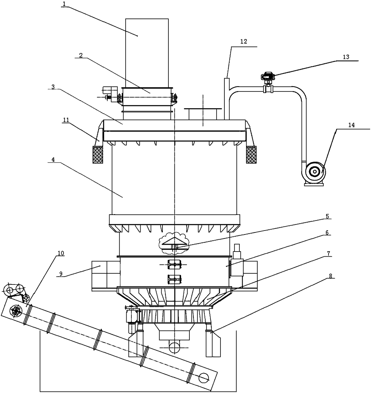
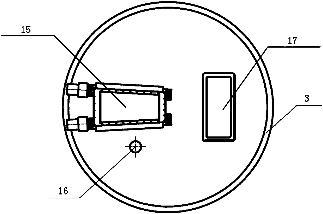
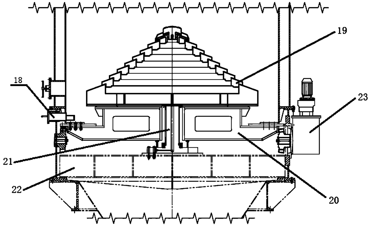
[0032] This embodiment provides a garbage pyrolysis gasification incinerator based on the present invention, and the overall structure schematic diagram of the incinerator can be referred to figure 1 with figure 2 , the incinerator comprises: a furnace body 4, a fire grate 5, and an air supply device arranged on the upper side of the furnace body 4; on the cover 3; the grate 5 is fixed on the lower part inside the furnace body 4, refer to image 3 , the grate 5 includes a multi-layer annular grid plate 19, the multi-layer annular grid plate 19 is stacked in a tower shape, and the multi-layer annular grid plate 19 is coaxially arranged.

[0033] The waste pyrolysis gasi...


PUM


Abstract

The invention provides a pyrolysis and gasification incinerator for garbage and a method. The incinerator comprises an incinerator body, a fire grate, and an air supplementing device which is arrangedat the upper side of the incinerator body, wherein a supplemented air inlet of the air supplementing device is formed in a cover at the upper end of the incinerator body; the fire grate, comprising amulti-layer annular grid tray, is fixed to the inner lower part of the incinerator body; the multi-layer annular grid tray is coaxially arranged and overlapped in a tower shape. According to the pyrolysis and gasification incinerator for the garbage and the method, the supplemented air inlet is formed in the cover, so that the combustion in the incinerator can be completely carried out, and as aresult, the incinerating efficiency can be improved; an upper area in the incinerator body can be used as a secondary combustion chamber, so that the used area can be greatly saved, and the design cost can be saved; the multi-layer annular grid tray of the fire grate is coaxially arranged; slag discharging and air supplying are independent and do not influence each other, so that dust can be smoothly discharged, and the supplied air can smoothly enter the incinerator, and as a result, the combustion in the incinerator is completely carried out, and the combustion efficiency is improved.

Description

technical field [0001] The invention relates to the technical field of solid waste pyrolysis incineration equipment, and more specifically, to a waste pyrolysis gasification incinerator and a method. Background technique [0002] With the continuous development of modern cities, urban domestic garbage and industrial solid waste are produced in large quantities, which has become a serious social pollution problem. At present, there are three ways to deal with solid waste: landfill, composting and incineration. Landfill not only takes up a lot of land, but also easily pollutes the surrounding environment. Composting cannot make the waste completely harmless, but only part of it. The method of incineration treatment is easy to realize the requirements of recycling, harmlessness and reduction of solid waste. [0003] Incineration and cement kiln co-processing of waste are currently widely used. There are three types of furnaces used for the co-processing of domestic waste in...

Claims


Application Information

Patent Timeline
Patent Type & Authority Applications(China)
IPC IPC(8): F23G5/00F23G5/027F23G5/14F23G5/44F23J3/00
CPCF23G5/002F23G5/0276F23G5/14F23G5/44F23J3/00
Inventor 顾军蔡文涛刘海兵
Owner BEIJING BUILDING MATERIALS ACADEMY OF SCI RES
Why Eureka
Try Eureka