Mold for vertical stepped pouring of rotary kiln burner and pouring method of mold

A burner and rotary kiln technology, which is applied in the field of refractory pouring, can solve the problems of restricting the operation cycle of rotary kiln, economic loss of enterprises, shutdown and maintenance, etc., and achieve the effects of saving pouring materials, increasing service life and reducing damage

Active Publication Date: 2018-06-29
HANDAN JINYU TAIHANG CEMENT
View PDF7 Cites 0 Cited by
  • Summary
  • Abstract
  • Description
  • Claims
  • Application Information

AI Technical Summary

Problems solved by technology

Rotary kiln burners are usually placed in the gas environment of high temperature and high wind speed in the kiln hood. They have been subjected to clinker particles for a long time and high-temperature gas erosion at 900-1200 ° C. They mainly rely on refractory castables for continuous protection. Once the refractory material In the event of damage, it is necessary to stop production for maintenance, resulting in economic losses to the enterprise
[0003] At present, the construction of burner refractory materials mainly adopts several forms such as assembled prefabricated parts, horizontal or split casting, etc., and its service life is usually only about 3-6 months, which seriously restricts the operation cycle of the rotary kiln

Method used


Image

  • Mold for vertical stepped pouring of rotary kiln burner and pouring method of mold
  • Mold for vertical stepped pouring of rotary kiln burner and pouring method of mold
  • Mold for vertical stepped pouring of rotary kiln burner and pouring method of mold

Examples


Embodiment 1

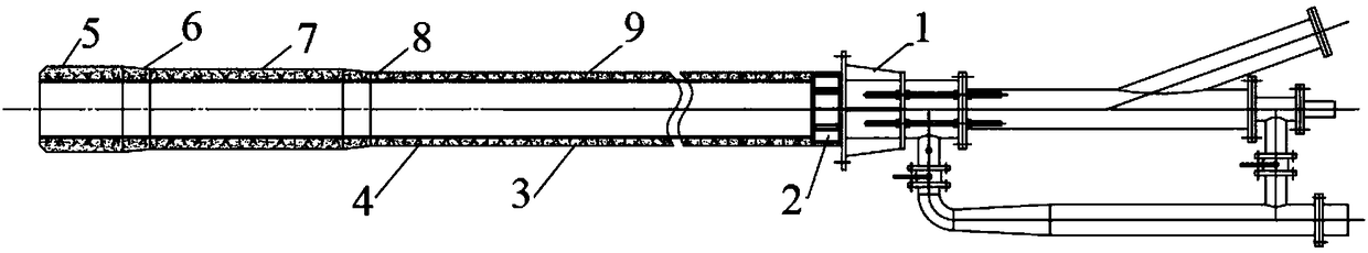
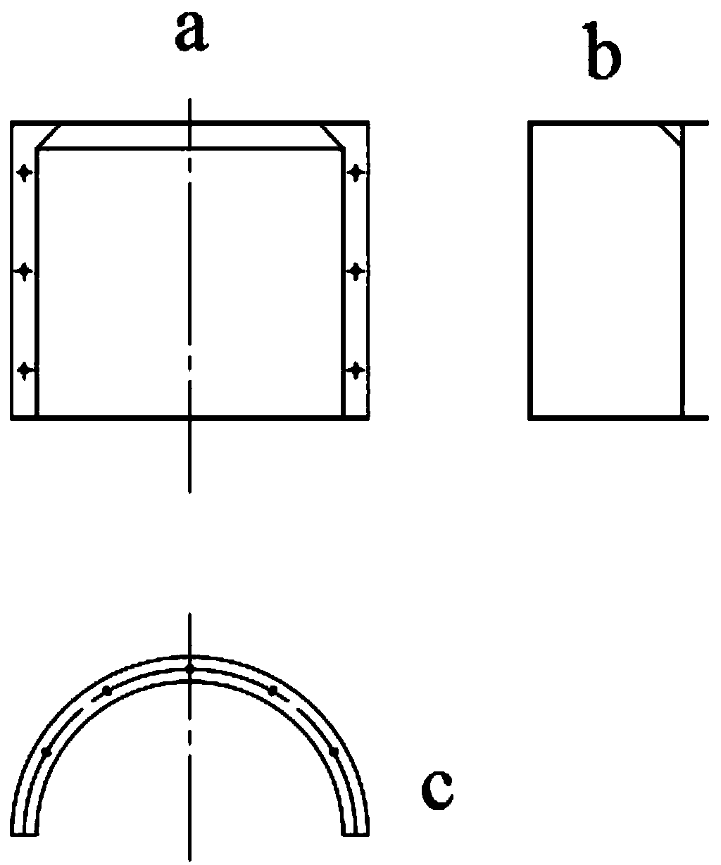
[0046] According to the characteristics of the burner used in the 2500t / d clinker production line, the mold template uses a 5mm thick iron plate in the shape of a semicircular arc surface, and two of them form a group, such as figure 2 Shown:

[0047] Mold 1: The length from the end of the burner is 600mm, the end has a 45° chamfer, and the quantity is 1 set;

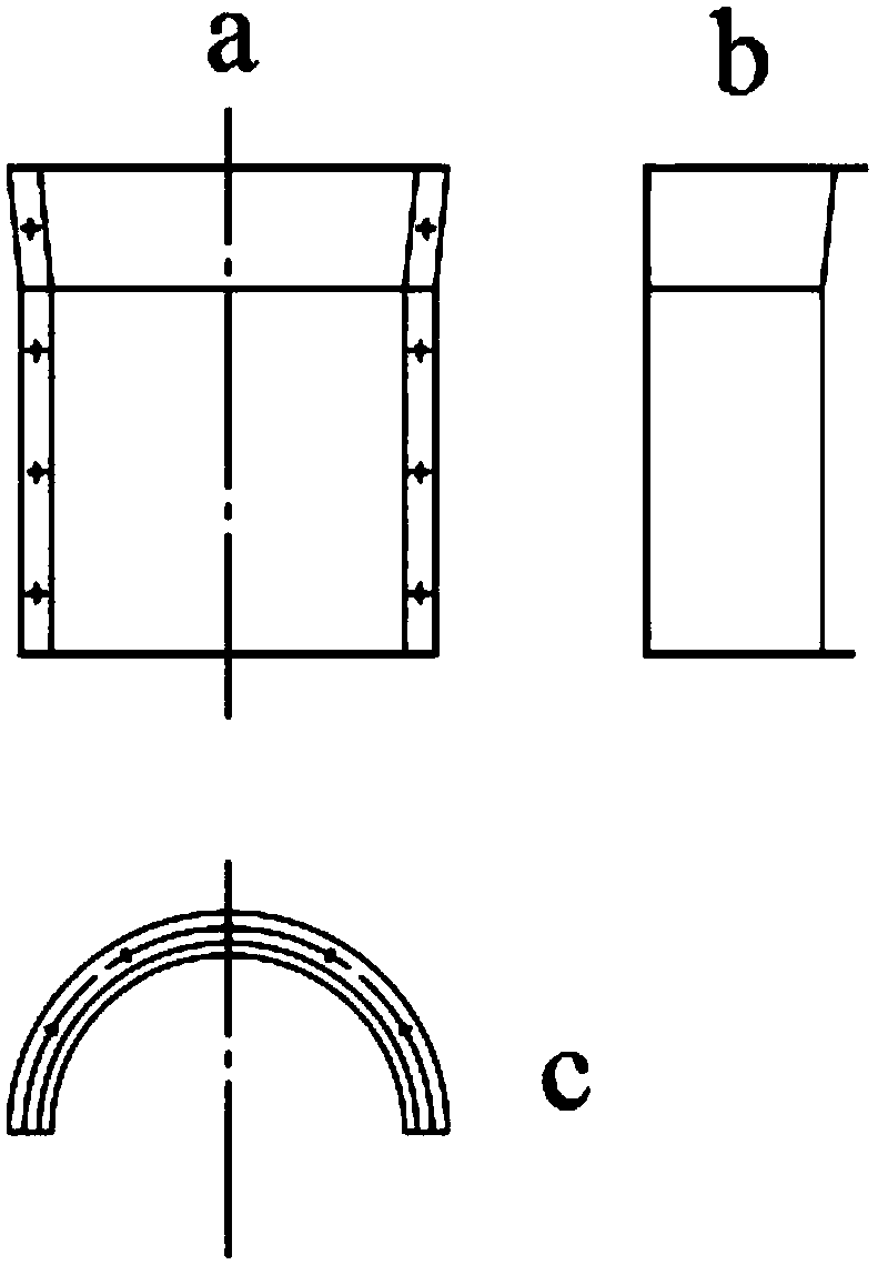
[0048]Variable diameter mold 1: length 800mm, quantity 1 set, connected with mold 1;

[0049] Mold 2: 800mm long, 1 set in quantity, connected with variable-diameter mold 1;

[0050] Variable diameter die 2: the length is 1000mm, the quantity is 1 group, connected with die 2;

[0051] Mold 3: The length is 1000mm, the quantity is 3 groups, and it is connected with the variable-diameter mold 2.

[0052] There are flanges on the four sides of each mold, and a layer of diesel oil is evenly painted inside the mold.

[0053] 1. Anchor welding

[0054] Clean the surface of the burner jacket 2, and the anchor piece 4 is ...


PUM

PropertyMeasurementUnit
thicknessaaaaaaaaaa
thicknessaaaaaaaaaa
lengthaaaaaaaaaa

Abstract

The invention relates to a mold for vertical stepped pouring of a rotary kiln burner. The mold includes five segments, namely, mold I, reducing mold II, mold II, reducing mold II and mold III from front to rear from the end of the rotary kiln burner, wherein the mold I is positioned at the end of the burner, and the end of the mold I is chamfered to 45 degrees, the reducing mold I is connected with the mold I, the mold II is connected with the reducing mold I, the reducing mold II is connected with the mold II, and the mold III is positioned behind the reducing mold II until the rear of the burner. The invention further relates to a vertical stepped pouring method of a rotary kiln burner, using the mold herein.

Description

technical field [0001] The invention belongs to the field of pouring refractory materials in the cement industry, and in particular relates to a vertical ladder pouring mold for a rotary kiln burner and a vertical ladder pouring method for a rotary kiln burner using the mold. Background technique [0002] The burner is one of the important thermal equipment in the cement clinker calcination process, and its service life directly affects the calcination quality and operation rate of the rotary kiln. Rotary kiln burners are usually placed in the gas environment of high temperature and high wind speed in the kiln hood. They have been subjected to clinker particles for a long time and high-temperature gas erosion at 900-1200 ° C. They mainly rely on refractory castables for continuous protection. Once the refractory material If it is damaged, it needs to stop production for maintenance, causing economic losses to the enterprise. [0003] At present, the construction of burner r...

Claims


Application Information

Patent Timeline
Patent Type & Authority Applications(China)
IPC IPC(8): B28B19/00B28B7/00B28B11/24
CPCB28B7/0029B28B11/24B28B19/0038
Inventor 张喜鹏李晶宋杰明孙瑞白永杰曹玉峰孙其龙
Owner HANDAN JINYU TAIHANG CEMENT
Why Eureka
Try Eureka