Eureka AIR delivers breakthrough ideas for toughest innovation challenges, trusted by R&D personnel around the world.

Device and method for manufacturing staggered cylinder metal card clothing

A technology of metal card clothing and cylinder, which is applied in deburring devices, textiles and papermaking, fiber processing, etc. It can solve the problems of uneven tension in the middle rack, 1.5mm, and tolerance control of ±0.02mm, which is difficult to control. Achieve the effects of avoiding wrong teeth and bad teeth, promising application prospects, and eliminating error accumulation

Active Publication Date: 2018-06-29
DONGHUA UNIV +1
View PDF7 Cites 1 Cited by
  • Summary
  • Abstract
  • Description
  • Claims
  • Application Information

AI Technical Summary

Problems solved by technology

Although the rack of the above-mentioned card clothing has a neat tooth shape after the gear punching device, the pin teeth can be rolled at intervals through a special post-processing mechanical device to form a misaligned arrangement of the pin teeth. However, if The continuous rolling of the ordinary roller device, that is, after punching the teeth, the rollers with raised blocks on the rotating surface are used to continuously roll the needle teeth, and the following problems will occur: (1) The pitch of the needle teeth is unavoidable For example, the tooth pitch is 1.5mm, and the tolerance control is ±0.02mm. Therefore, after a period of accumulation, rolling misaligned teeth at a fixed position may cause wrong rolling, or even cause bad teeth; (2) The rack travel process In the middle, the distance between the feeding area and the winding area is very far, and the tension of the middle rack may be uneven, resulting in a gradual deviation of the position of the rack. After accumulation, it will also cause wrong rolling or even bad teeth.
In the practice of this method of production, the card clothing will accumulate a pitch error after 30 to 50 needle teeth. The accumulation of errors comes from a wide range of sources and is difficult to control.

Method used

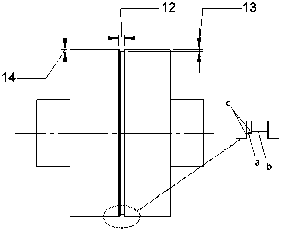
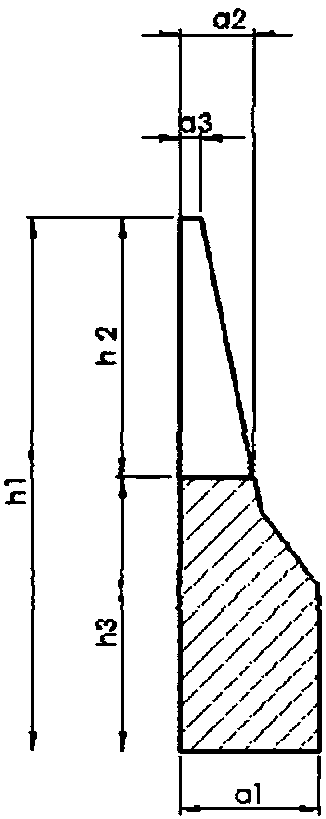

Image

  • Device and method for manufacturing staggered cylinder metal card clothing
  • Device and method for manufacturing staggered cylinder metal card clothing
  • Device and method for manufacturing staggered cylinder metal card clothing

Examples


Embodiment 1

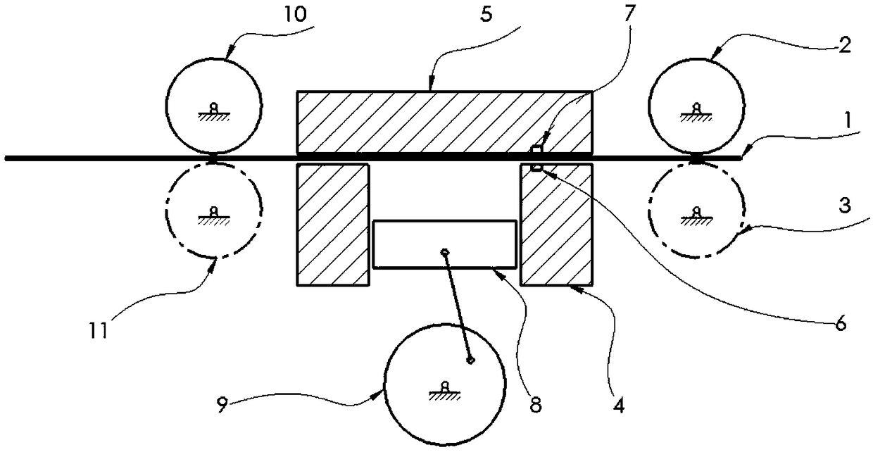
[0040] A device for making misplaced cylinder metal card clothing, such as figure 1 As shown, it includes two pairs of pressure rollers arranged up and down, that is, the rear upper pressure roller 2, the rear lower pressure roller 3, the front upper pressure roller 10 and the front lower pressure roller 11, and the extrusion box between the two pairs of pressure rollers, The extrusion box includes an upper pressing plate 5, a lower pressing plate 8 and a positioning seat 4 arranged under the upper pressing plate 5, and the upper side of the slider part of the crank slider mechanism 9 that drives the lower pressing plate 8 to move up and down is connected with the lower pressing plate 8 through a T-shaped groove. , the positioning seat 4 is located on the side of the lower platen 8 .

[0041] Among the two pairs of pressure rollers, the rear upper pressure roller 2 and the front upper pressure roller 10 are surrounded by stepped grooves that limit the rack 1 in the straight ru...

Embodiment 2

[0048] A device for making dislocated cylinder metal card clothing, the structure of which is basically the same as that of Embodiment 1, the difference is that for (N+1) dislocated cylinder metal card clothing, when the surface of the upper platen 5 opposite to the lower platen 8 is set When groove channel 16 and protruding block 17 are arranged, the height of groove channel 16 in upper pressing plate 5 or lower pressing plate 8 is equal to 1 / 2 of the base width of tooth bar 1, and the width of groove channel 16 is equal to the total of tooth bar 1. Tooth height.

[0049] The total number of raised blocks 17 in the upper pressing plate 5 and the lower pressing plate 8 is an integer multiple of 2N, and every 2N raised blocks 17 is a period, and the arrangement is N raised blocks 17 of the lower pressing plate 8 and the upper pressing plate 5 The N protruding blocks 17 are arranged alternately, and the protruding blocks 17 of the upper platen 5 and the lower platen 8 are arrang...


PUM


Abstract

The invention discloses a device and method for manufacturing staggered cylinder metal card clothing. The device comprises two pairs of vertically distributed pressing rollers and a squeezing box located between the two pairs of pressing rollers. The squeezing box comprises an upper pressing plate, a lower pressing plate and a positioning base. Grooves are formed around the circumferences of the upper pressing rollers of the two pairs of pressing rollers. A groove channel is formed in the lower pressing plate and internally provided with a plurality of protruding blocks for squeezing needle teeth. The opposite faces of the upper pressing plate and the positioning base are provided with a transmitting end and a receiving end of a photoelectric sensor respectively. A counter is installed inthe positioning base. The counter, the two pairs of pressing rollers and a mechanism which is used for driving the lower pressing plate to move up and down are connected with an electronic control unit. The manufacturing method includes the step that after being fed from one pair of vertically distributed pressing rollers into the squeezing box for staggered rolling, a rack is output by the otherpair of vertically distributed pressing rollers to prepare the staggered cylinder metal card clothing. By means of the device and method, the error accumulation of the pitch of teeth is eliminated, tooth staggering and breakage phenomena are effectively avoided, and the produced card clothing is excellent in quality and has great application prospects.

Description

technical field [0001] The invention belongs to the technical field of textile machinery, and in particular relates to a device and a method for making dislocated cylinder metal card clothing. Background technique [0002] Metal card clothing is also called metal saw blade, the pin teeth and the base are integrated, and the structure is simple. The tip of the tooth is big like a zigzag, and the small one is like a fine needle. The density is higher than that of elastic card clothing, but the tooth depth is shallower. It has strong spinning performance and a wide range of applications. It is suitable for carding machine cylinders, carding machine cylinders, Stripping rollers, licker-in rollers and doffers. The metal card clothing is made of high-quality carbon steel or low-alloy steel. The metallographic structure of the tooth tip after quenching is first-grade fine acicular martensite, and the base is relatively soft, which is spherical pearlite, which can make the wrapping...

Claims


Application Information

Patent Timeline
IPC IPC(8): D01G15/88
Inventor 和杉杉程隆棣刘蕴莹薛文良张瑞云俞建勇王克毅陆忠朱玉飞张淑慧侯令晨
Owner DONGHUA UNIV
Why Eureka
Eureka Blog
Learn More