
Multi-echo multi-slice spatio-temporal encoding magnetic resonance imaging method based on segmented excitation

A technology of magnetic resonance imaging and spatio-temporal coding, which is used in the measurement of magnetic variables, measuring devices, instruments, etc., can solve the problems of images being easily affected by eddy current effects, high absorption rate of linear sweep pulses, and limited applications, and achieves enhanced resistance to Capability of inhomogeneous magnetic fields and chemical shift effects, reduced sampling time, effect of slowing down effects

Active Publication Date: 2020-01-14
XIAMEN UNIV
View PDF6 Cites 0 Cited by
  • Summary
  • Abstract
  • Description
  • Claims
  • Application Information

AI Technical Summary

Problems solved by technology

However, the current spatio-temporal encoding imaging method still has the following defects: First, due to the fast positive and negative gradient switching in the sampling stage for data acquisition, the image is susceptible to artifacts caused by the eddy current effect [16,17] Second, the specific absorption rate (SAR) of the linear sweep pulse used in space-time coding is relatively large, which has no effect on single-slice imaging, but in multi-layer imaging, the repeated application of linear sweep pulses will cause the SAR value to be too large, thus limiting its application in clinical

Method used


Image

  • Multi-echo multi-slice spatio-temporal encoding magnetic resonance imaging method based on segmented excitation
  • Multi-echo multi-slice spatio-temporal encoding magnetic resonance imaging method based on segmented excitation
  • Multi-echo multi-slice spatio-temporal encoding magnetic resonance imaging method based on segmented excitation

Examples


specific Embodiment

[0084] The experiments in this example were performed on a Varian 7T imager (Agilent Technologies, Santa Clara, CA, USA), and the samples were rats. The steps are as follows: Prepare live rats, first use isoflurane mixed with oxygen to quickly anesthetize the rats, then place the rats on the experimental bed and fix them, and continue to use low-concentration isoflurane mixed with oxygen to maintain the anesthetized state of the rats. The test bed is sent into the detection chamber of the magnetic resonance imaging machine. Open the operating software on the operating table of the magnetic resonance imager, first locate the region of interest of the sample to be tested, and then perform tuning, frequency correction, power correction and automatic shimming on the imager. In order to evaluate this method, multi-scan gradient echo imaging, multi-layer spin echo EPI, multi-layer double-echo EPI, and multi-layer segmental space-time coding imaging experiments were carried out in th...


PUM


Abstract

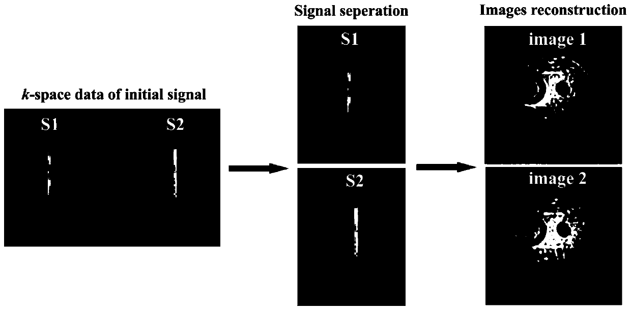
The invention discloses a segmented excitation based multi-echo multi-layer space-time coding magnetic resonance imaging method, and relates to a magnetic resonance imaging method. The method comprises the following steps: dividing an imaging object into several segments; selecting an imaging segment through a 90-degree segment selection pulse; performing time-space coding of intra-segment core spinning through a 180-degree linear frequency sweep pulse; enabling the core of non-imaging segment to spin to a heat balance state by using a 180-degree hard pulse; storing the spinning information byusing the same pulse as the 90-degree segment selection pulse; sequentially exciting multiple target layers by using multiple 90-degree layer selection pulses; in combination with the specific dispersed phase gradient of frequency coding dimension, enabling the signals on different layers to form echoes at different sampling moments; changing the center frequency of the layer selection pulse andrelevant pulse gradient, to obtain magnetic resonance data on each layer in the segment; modifying the center frequency of the segment selection pulse, and selecting different imaging segments; repeating the above operations to obtain data of the whole imaging object; dividing the data of multiple echoes acquired at the same time, according to the echo number; and performing super-resolution reconstruction of the data on each layer, to obtain a multi-layer high-resolution magnetic resonance image.

Description

technical field [0001] The invention relates to a magnetic resonance imaging method, in particular to a multi-echo multi-layer space-time encoding magnetic resonance imaging method based on segmental excitation. Background technique [0002] Ultra-fast magnetic resonance imaging (MRI) has good temporal resolution, and it is very useful in functional MRI (fMRI) [1-3] , Diffusion tensor imaging (DTI) [4-6] , free-breathing heart imaging [7] and other fields play an important role. In ultra-fast MRI, echo planar imaging (EPI) is currently the most widely used, and it has excellent performance in both temporal and spatial resolution. [8-10] . EPI is sampled through a series of rapidly switched gradient echoes, and all the data required for a two-dimensional magnetic resonance image can be obtained with one radio frequency pulse excitation. However, EPI images are susceptible to distortion due to inhomogeneous magnetic fields and chemical shift effects [11,12] . [0003] I...

Claims


Application Information

Patent Timeline
Patent Type & Authority Patents(China)
IPC IPC(8): G01R33/565G01R33/561
CPCG01R33/5615G01R33/56518G01R33/56527G01R33/56554
Inventor 蔡淑惠罗瑶张俊蔡聪波
Owner XIAMEN UNIV
Learn More