

Echo signal generating method for radio altimeter
A technology of radio altimeter and echo signal, which is applied in radio wave measurement system, radio wave reflection/re-radiation, utilization of re-radiation, etc. It can solve problems such as echo simulation and testing are difficult to implement, and achieve code upgrade and update Convenience, small size, high integration effect
Active Publication Date: 2018-06-29
UNIV OF ELECTRONICS SCI & TECH OF CHINA
View PDF8 Cites 2 Cited by
- Summary
- Abstract
- Description
- Claims
- Application Information
AI Technical Summary
Problems solved by technology
Traditional test instruments usually only perform decomposition tests of functional modules, or use surface acoustic wave filters, traveling wave tubes, electronic delay lines, and optical fiber delay lines to achieve signal delay and simulation. It is difficult to realize the echo simulation and test of the influence factors such as the Doppler frequency shift and the multipath effect of the reflected echo.
Method used
View moreImage
Smart ImageViewing Examples

Examples
Embodiment
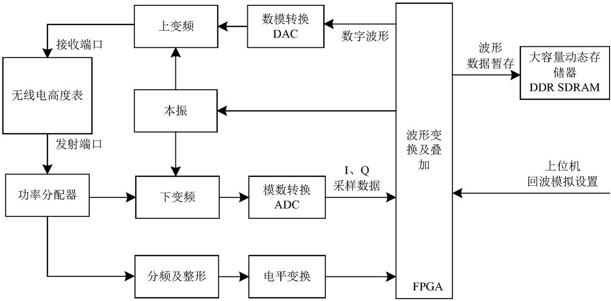
[0029] figure 1 It is a principle diagram of the echo signal generation method of a radio altimeter of the present invention.
[0030] In this example, if figure 1 Shown, the echo signal generation method of a kind of radio altimeter of the present invention comprises the following steps:
[0031] S1, signal preprocessing
Login to View More PUM
 Abstract
The invention discloses an echo signal generating method for a radio altimeter. The echo signal generating method comprises the following steps of waveform collection storage, data delay forwarding, high-order scene feature overlaying, echo analog generation and the like, and are realized by adopting auxiliary devices of a programmable device FPGA (Field Programmable Gate Array) and ADC (Analog toDigital Converter), DAC (Digital-to-Analog Converter), DDR, SDRAM (Synchronous Dynamic Random Access Memory) and the like; emulation for two kinds namely continuous wave and impulse type of radio altimeter echoes can be realized, so that the function and index test of the DUT can be finished, and high extensibility and flexibility are achieved.
Description
technical field [0001] The invention belongs to the technical field of signal generation and processing, and more specifically relates to a method for generating an echo signal of a radio altimeter. Background technique [0002] Radio altimeter, also called radar altimeter. It is a kind of height measuring equipment widely equipped and used in various types of aviation and aerospace equipment. Radio altimeters can be divided into three categories: space-borne, missile-borne and airborne according to the different bodies. Distinguished from the type of transmitted signal, radio altimeters can be divided into two categories: pulse type and continuous wave. The basic working principle of the radio altimeter is to transmit the altimeter signal, and then receive the echo signal reflected from the target surface, and calculate the propagation time of the signal to obtain the height or distance between the carrier equipment and the target surface. Early radio altimeters can only...
Claims
Login to View More Application Information
Patent Timeline
 Patent Type & Authority Applications(China)
IPC IPC(8): G01S7/40G01S13/88
CPCG01S7/4052G01S13/882G01S7/4065
Inventor 张朋李力黄建国
Owner UNIV OF ELECTRONICS SCI & TECH OF CHINA