
An ultrasonic impact shot peening device

A technology of shot blasting device and ultrasonic impact, applied in furnaces, heat treatment equipment, heat treatment furnaces, etc., can solve problems such as surface damage, failure damage, etc., and achieve reliable performance, simple structure, and high efficiency

Active Publication Date: 2019-08-02
宏阔(南通)智能装备有限公司
View PDF3 Cites 0 Cited by
  • Summary
  • Abstract
  • Description
  • Claims
  • Application Information

AI Technical Summary

Problems solved by technology

[0003] In practical application, the impact treatment methods using ultrasound as the power source in the prior art all require the impact striker to be in rigid contact with the object to be treated and the horn to realize the continuous movement of the striker. Under this working condition, the amplitude The ultrasonic vibration of the rod directly acts on the surface of the object to be processed through the striker. Under the direct rigid impact of high-frequency ultrasonic vibration, the surface of the object to be processed is easily damaged severely, and even causes its failure and damage.

Method used


Image

  • An ultrasonic impact shot peening device
  • An ultrasonic impact shot peening device
  • An ultrasonic impact shot peening device

Examples


Embodiment Construction

[0023] Embodiments of the ultrasonic impact peening device of the present invention will be described below with reference to the accompanying drawings. Those skilled in the art would recognize that the described embodiments can be modified in various ways or combinations thereof without departing from the spirit and scope of the invention. Accordingly, the drawings and description are illustrative in nature and not intended to limit the scope of the claims. Also, in this specification, the drawings are not drawn to scale, and like reference numerals denote like parts.

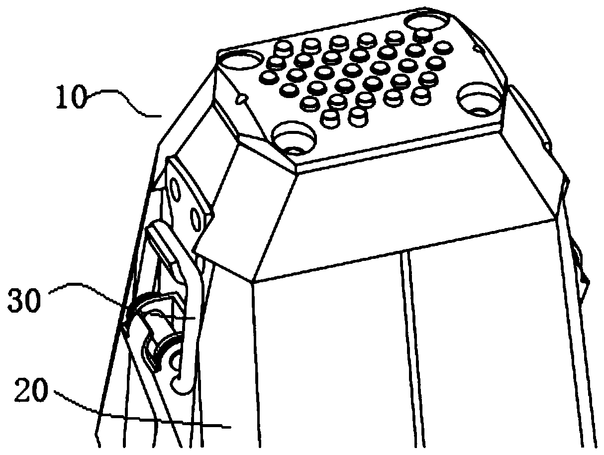
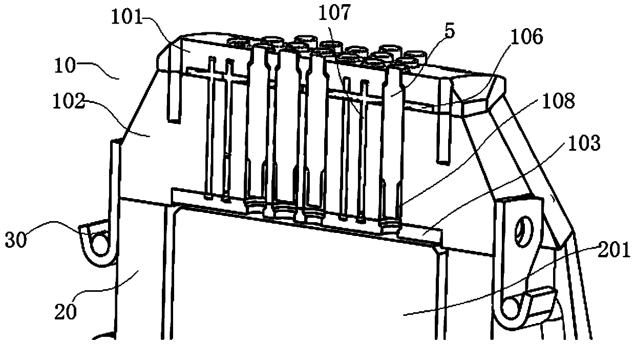
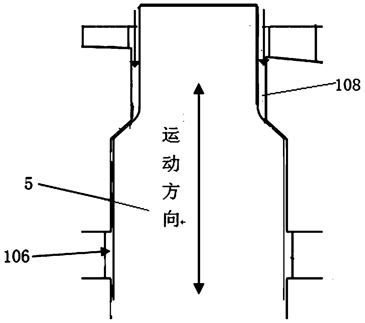
[0024] Such as figure 1 , figure 2 As shown, the ultrasonic impact peening device of this embodiment includes an impact gun 20 , an impact head 10 and a striker 5 installed in the impact head 10 . A transducer is arranged in the impact gun 20, and the impact head 10 is connected with the impact gun 20, so that there is a certain gap between one end of the impact head 10 and the end face of the horn 201 of ...


PUM


Abstract

An ultrasonic impact shot blasting device comprises an impact gun and an impact head. A transducer is arranged in the impact gun. The impact head is connected with the impact gun. A gap is formed between one end of the impact head and the end face of an amplitude-change pole of the transducer. At least one cavity penetrating the impact head in the vibration direction of the amplitude-change pole is formed in the impact head. A striker is arranged in each cavity. The strikers are driven under the action of vibration of the amplitude-change pole to be ejected toward the ends, far away from the amplitude-change pole, of the corresponding cavities. At the maximum working stroke of the strikers, the ends, far away from the amplitude-change pole, of the strikers extend out of the corresponding cavities and impact the surface of a workpiece. The strikers rebound in the direction of the amplitude-change pole till the ends, near the amplitude-change pole, of the strikers are in contact with andcollide with the amplitude-change pole, so that the strikers are made to be ejected back and forth between the amplitude-change pole and the workpiece. When the strikers collide with the workpiece, negative pressure suction is adopted to enhance the rebound effect of the strikers, and ultrasonic vibration and vacuum power are combined to realize the autonomous reciprocating motion of the strikers. The strikers collide with the workpiece elastically, the impact treatment effect is ensured, and damage to the surface quality is avoided.

Description

technical field [0001] The invention relates to the field of ultrasonic technology, in particular to an ultrasonic impact shot peening device. Background technique [0002] In the process of metal processing, metal welding is a commonly used processing method. After metal materials are welded according to specific shapes and sizes, due to the joint action of factors such as the stress concentration of the weld toe and the residual tensile stress, the fatigue performance of the welded joint is generally higher than that of the welded joint. Far below the base metal, welding fatigue cracks usually originate at the weld toe of the joint, resulting in accidents of large-scale welded structural parts such as offshore oil drilling platforms, bridges, ships, aircraft, and rolling stock, which pose a threat to people's personal safety. , Work, travel, life, property and other aspects have brought serious threats. Therefore, improving the fatigue strength of welded joints has become...

Claims


Application Information

Patent Timeline
Patent Type & Authority Patents(China)
IPC IPC(8): C21D7/06C21D9/50
CPCC21D7/06C21D9/50
Inventor 孟宪林尚晓峰
Owner 宏阔(南通)智能装备有限公司
Learn More