Covered stent
A covered stent and film-covered technology, applied in stents, medical science, blood vessels, etc., can solve the problems of guide wires entering the window, stent displacement and thrombus, and long operation time, so as to shorten operation time and reduce branch artery damage and stenosis, the effect of reducing the probability of occurrence
- Summary
- Abstract
- Description
- Claims
- Application Information
AI Technical Summary
Problems solved by technology
Method used
Image
Examples
no. 1 example
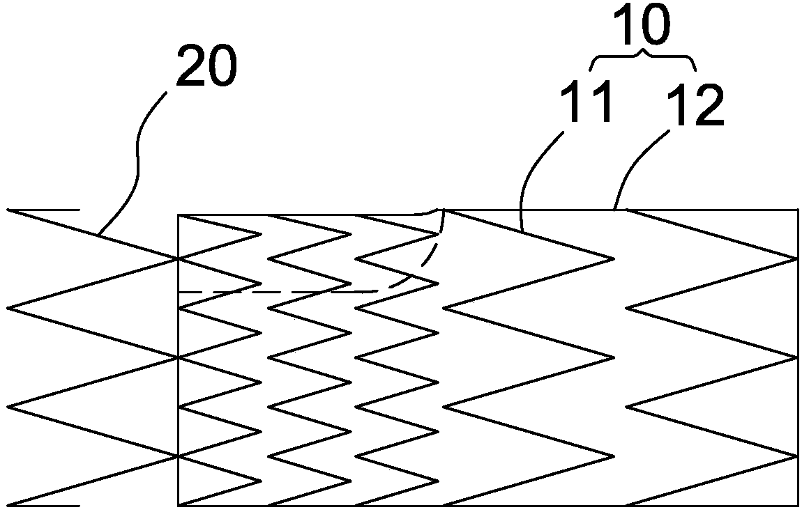
[0060] Such as image 3 and Figure 4 As shown, the stent-graft of the present invention includes a stent-graft segment 10 and a bare stent segment 20 connected to the proximal end of the stent-graft 10 . The stent graft segment 10 includes a stent body 11 and a membrane 12 covering the stent body 11 . The stent graft has the ability to expand radially, and can be compressed under external force and self-expand after the external force is removed or return to the original shape by mechanical expansion (such as balloon expansion) and maintain the original shape, so that after implanting in the lumen It can be fixed in the lumen by being close to the lumen wall through its radial support force, so as to reconstruct the blood flow channel and isolate the lesion.
[0061] Such as Figure 5-7 As shown, the membrane 12 is a hollow lumen structure with both ends open, and the lumen structure constitutes a channel for blood flow. The covering film 12 itself has a certain thickness...
no. 2 example
[0067] Such as Figure 13 and Figure 14 As shown, in this embodiment, the structure and function of the stent graft are the same as those in the previous embodiment, the difference is that the groove 21 on the film 20 in this embodiment is different from the previous embodiment. The groove 21 still includes a first curved surface 211 extending from the proximal end of the stent-graft along the axis of the stent-graft and a second curved surface 212 connected to the first curved surface 211 . Such as Figure 15 As shown, different from the previous embodiment, the first curved surface 211 includes two opposite planes 213 vertically extending toward the inside of the stent-graft and a semi-cylindrical surface 214 connecting the edges of the two planes 213 . The first curved surface 211 mainly supporting the branch bracket makes the groove 21 have a U-shaped cross-section. In this embodiment, the two planes 213 are arranged in parallel and at intervals, and the distance betwe...
no. 3 example
[0069] Such as Figure 16-18 As shown, in this embodiment, the structure and function of the stent graft are the same as those in the previous embodiment, the difference is that the groove 31 on the film 30 in this embodiment is different from the previous embodiment. The groove 31 still includes a first curved surface 311 extending from the proximal end of the stent-graft along the axis of the stent-graft and a second curved surface 312 connected to the first curved surface 311 . Such as Figure 18 As shown, the difference from the previous embodiment is that the first curved surface 311 includes two opposite planes 313 extending toward the inside of the stent-graft and an elliptical cylindrical surface 314 connecting the edges of the two planes 313 . The first curved surface 311 mainly supporting the branch bracket makes the cross-sectional shape of the groove 31 roughly U-shaped. In this embodiment, the two planes 313 are arranged in parallel and at intervals, and the dis...
PUM
 Abstract
Description
Claims
Application Information
 - R&D
- Intellectual Property
- Life Sciences
- Materials
- Tech Scout
- Unparalleled Data Quality
- Higher Quality Content
- 60% Fewer Hallucinations
Browse by: Latest US Patents, China's latest patents, Technical Efficacy Thesaurus, Application Domain, Technology Topic, Popular Technical Reports.
© 2025 PatSnap. All rights reserved.Legal|Privacy policy|Modern Slavery Act Transparency Statement|Sitemap|About US| Contact US: help@patsnap.com


