
Micro-hole vortex sleeve mixing reactor and application thereof

A mixed reactor and microporous technology, applied in chemical/physical/physical chemical reactors, chemical instruments and methods, chemical/physical/physical chemical processes, etc., can solve blockage, amplification limitation, limited temperature and pressure resistance problems and other problems, to achieve the effect of enhancing mass transfer and heat transfer, avoiding clogging problems, and high substrate concentration

Active Publication Date: 2018-07-06
睦化(上海)流体工程有限公司
View PDF14 Cites 10 Cited by
  • Summary
  • Abstract
  • Description
  • Claims
  • Application Information

AI Technical Summary

Problems solved by technology

At present, there are basically two types of casing microchannel reactors reported in the literature or commercially available: 1) A type of membrane dispersed reactor uses traditional sintered metal or wire mesh microporous filter membranes to disperse the fluid into tiny bubbles or droplets , so as to strengthen the microscopic mass transfer and heat transfer process, but the pore size and distribution of conventional sintered materials are disordered and randomly formed, and generally can only form a jet flow uniformly distributed within a certain range in the circumferential direction of the tube wall, which can be applied to gas-liquid two-phase mixing Or liquid-liquid mixed into emulsion or liquid-liquid to form solid precipitation reaction to synthesize micro-nano particles
However, for the application of liquid-liquid formation of solid precipitation reaction to synthesize micro-nano particles, there is still a large risk of clogging, and it is impossible to systematically design the size and distribution of the micropores and the spray direction of the micropores relative to the tube wall to form a vortex.
2) Another type of microporous material using Teflon (such as AF-2400) is designed as a tube-in-tube reactor (“tube-in-tubereactor”) after a polymer inner tube made of a variety of gas permeability but good liquid tightness, but is limited by polymerization Due to the characteristics of the material (temperature and pressure resistance problems in large sizes, etc.), the sleeve reactor has only been successfully developed at the laboratory level, and it is only suitable for gas-liquid two-phase mixed heat exchange.
However, neither of the above two patents described the process channel and its geometric structure of the dispersed phase and the continuous phase, nor did it mention the concept of the sleeve microchannel reactor
[0006] Chinese patent 001057790 discloses a membrane dispersing extractor, which is equipped with a membrane tube or a flat membrane in a cylindrical barrel, and has micropores of 0.01-60 microns on the membrane, which disperses the liquid into tiny droplets, increasing the The large mass transfer area improves the extraction effect, but the extractor is for the purpose of extraction and lacks the micro-size restriction after fluid contact, so it is not suitable for the process of rapid reaction synthesis of nanoparticles
However, since microporous membranes are generally sintered porous materials or wire mesh made of spherical or irregularly shaped metal or alloy powders after forming and sintering, the random or evenly distributed preparation process of the micropores will limit the size and spacing of membrane pores. The controllability of the two-phase mixed mass transfer affects the efficiency of the two-phase mixed mass transfer; in addition, the length of the microporous membrane section is limited (generally 10-20mm), and there is no other means to further strengthen the mixing after the two-phase cross-flow contact in the early stage, especially for the precipitation method The process of preparing nanoparticles may cause blockage in the annular microchannel
[0008] In summary, the sleeve-type microchannel mixers / reactors reported in the literature or commercially available at present, no matter whether they use sintered metal or wire mesh microporous membranes or use special polymer microporous tubes, generally only have a certain amount of water in the circumferential direction of the tube wall. The jet flow is formed uniformly or randomly in the range, and it is difficult to design the system for the size and distribution of the microholes and the jet direction of the microholes relative to the tube wall to form vortices and turbulent flows
The casing micro-mixer made of polymer microporous tube is only suitable for gas-liquid mixing process and the scale is limited; although the casing micro-mixer made of sintered metal or wire mesh can also be used for liquid-liquid formation of solid precipitation synthesis micro-mixer Nanoparticles, but there is still a considerable risk of clogging due to the lack of additional mixing means in the annular channel

Method used


Image

  • Micro-hole vortex sleeve mixing reactor and application thereof
  • Micro-hole vortex sleeve mixing reactor and application thereof
  • Micro-hole vortex sleeve mixing reactor and application thereof

Examples


Embodiment 1

[0075] like Figure 4 Shown is a schematic diagram of the structure of multiple groups of discontinuous micropore arrays, which are composed of multiple groups of arcs parallel to the cross-section on the tube wall. Clockwise spiral; it can also be composed of multiple groups of straight line segments parallel to the axial direction, and these straight line segments progress in turn in the radial and axial directions to present a clockwise or counterclockwise spiral in the circumferential direction of the pipe wall; it can also be composed of neither parallel It is composed of multiple groups of arcs whose cross-section is not parallel to the circumferential direction. Similarly, these arcs progress in turn in the axial direction and present a clockwise or counterclockwise spiral in the circumferential direction of the pipe wall, or clockwise and counterclockwise spirals. A combination of different orders; it can also be formed by combining the various arcs or straight line se...

Embodiment 2

[0081] like Figure 5 As shown, it is a continuous group of micropore arrays, which is composed of multiple sets of arcs parallel to the cross section on the tube wall and multiple sets of straight line segments parallel to the axial direction. These arcs and straight line segments are combined in the axial direction Sequential progression presents a clockwise or counterclockwise spiral in the circumferential direction of the pipe wall; it can also be composed of multiple groups of straight line segments parallel to the axial direction and multiple groups of arcs connected to the pipe wall not parallel to the cross section. The combination of arcs and arcs progresses in turn along the axial direction, showing a clockwise or counterclockwise spiral in the circumferential direction of the pipe wall; it can also be composed of multiple groups of arcs parallel to the cross-section on the pipe wall and multiple groups of arcs not parallel to the axial direction. It is composed of c...

Embodiment 3

[0090] like Image 6 shown is a continuous array of micropores, consisting of sets of arcs that are neither parallel to the cross-section nor parallel to the axial direction, these arcs are parallel to each other like coils wound around the circumference of the tube wall distribution, these arc combinations progress in turn in the axial direction and present a clockwise or counterclockwise spiral in the circumferential direction of the pipe wall; it can also be a combination of clockwise and counterclockwise spirals in different orders and length ratios.

[0091] Image 6 The arrays of mesopores are progressively progressive along the axial direction, showing a counterclockwise or clockwise spiral in the circumferential direction of the tube wall, and the dashed part shows the arc or straight line segment on the back of the inner tube wall:

[0092] (j) Similar to the counterclockwise spiral continuous multiple groups of micropore arrays distributed in parallel between the co...


PUM


Abstract

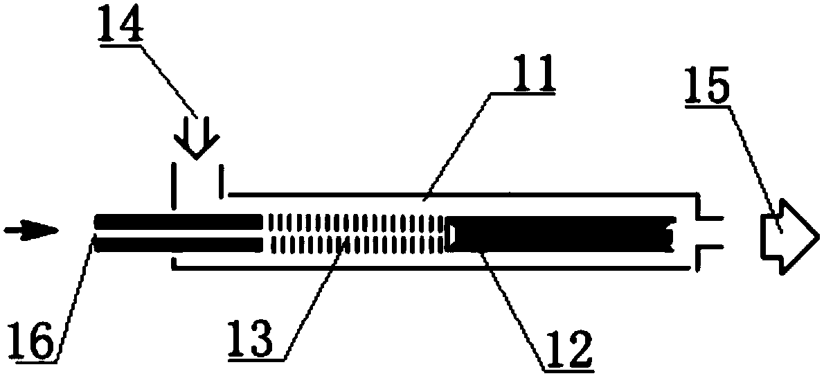
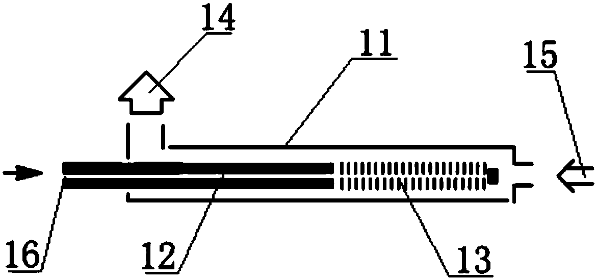
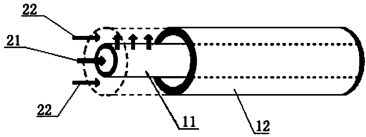
The invention provides a micro-hole vortex sleeve mixing reactor and application thereof. The micro-hole vortex sleeve mixing reactor comprises a concentric sleeve consisting of an outer pipe and an inner pipe, wherein an annular channel is formed between the inner pipe and the outer pipe; the outer pipe is provided with a continuous phase inlet and an outlet; one end of the inner pipe is a dispersion phase inlet, and the other end of the inner pipe is a closed end; a group of continuous micro-hole arrays or multiple groups of discontinuous micro-hole arrays are distributed between two ends ofthe inner pipe along the circumferential direction and the axial direction of the pipe wall; when a dispersion phase enters a continuous phase, vortex is formed in the annular channel. Compared withan existing sleeve type micro-channel mixer, the micro-hole vortex sleeve mixing reactor provided by the invention has the advantages that stronger micromixing is guaranteed under high treatment capacity or a higher substrate concentration; due to the formation of the vortex, the problem of blockage of small solid particles possibly produced in the process can be effectively relieved or avoided.

Description

technical field [0001] The invention relates to a microporous vortex sleeve mixing reactor, and the invention also relates to the application of a microporous vortex sleeve mixing reactor, which belongs to the field of chemical industry. Background technique [0002] Regarding gas-liquid mixing or gas absorption, and liquid-liquid mixing, especially the reaction of water-oil two-phase mixing or liquid-liquid mixing to produce solid precipitated small particles, in literature or industry, in addition to designing fluid distributors, such as Chinese patent CN200810011995.6, the use of fluid Combination of distributor and mixed microchannel technology, falling film reactor or using shell and tube design, also has inner and outer tube-in-tube design, in which two fluids are input through the inner and outer tubes, and the annular channel formed in the inner and outer tubes Process engineering for mass transfer and heat exchange in the process of gas absorption or liquid-liquid m...

Claims


Application Information

Patent Timeline
Patent Type & Authority Applications(China)
IPC IPC(8): B01J19/00
CPCB01J19/0053B01J19/0093B01J2219/00889B01J2219/00797
Inventor 刘翠芳邓菊莲
Owner 睦化(上海)流体工程有限公司
Learn More