Centrifugal type micro-fluidic chip

A microfluidic chip and centrifugal technology, which is applied in the field of life science and medical testing, can solve the problems of increasing the complexity of chip manufacturing and processing costs, affecting liquids, and not completely solving the problem of uniform distribution of air bubbles in samples, so as to avoid cross-contamination of samples , uniform distribution, and uniform flow rate

Pending Publication Date: 2018-07-06
杭州殷欣病理诊断中心有限公司
View PDF2 Cites 4 Cited by
  • Summary
  • Abstract
  • Description
  • Claims
  • Application Information

AI Technical Summary

Problems solved by technology

However, the channel section design of the chip’s main channel with narrow peaks and wide troughs affects the flow rate of the liquid in the main channel, which cannot completel

Method used


Image

  • Centrifugal type micro-fluidic chip
  • Centrifugal type micro-fluidic chip
  • Centrifugal type micro-fluidic chip

Examples


Embodiment

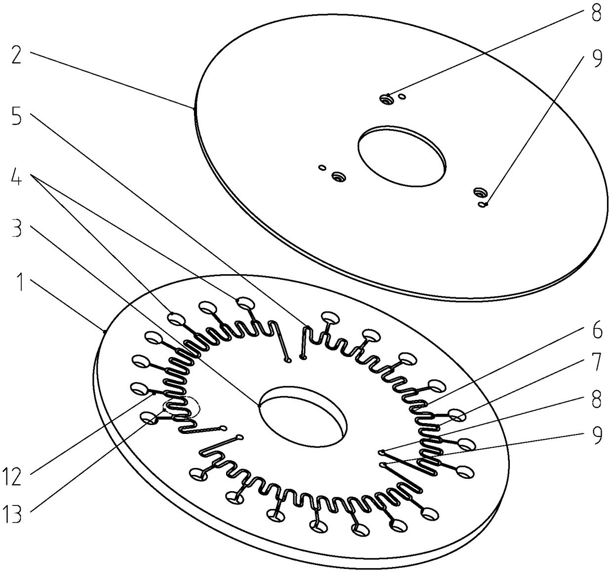
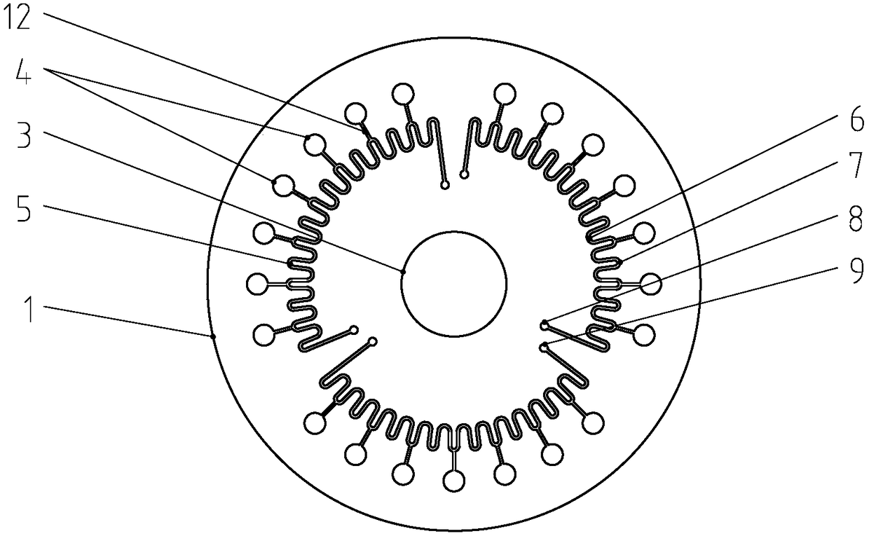
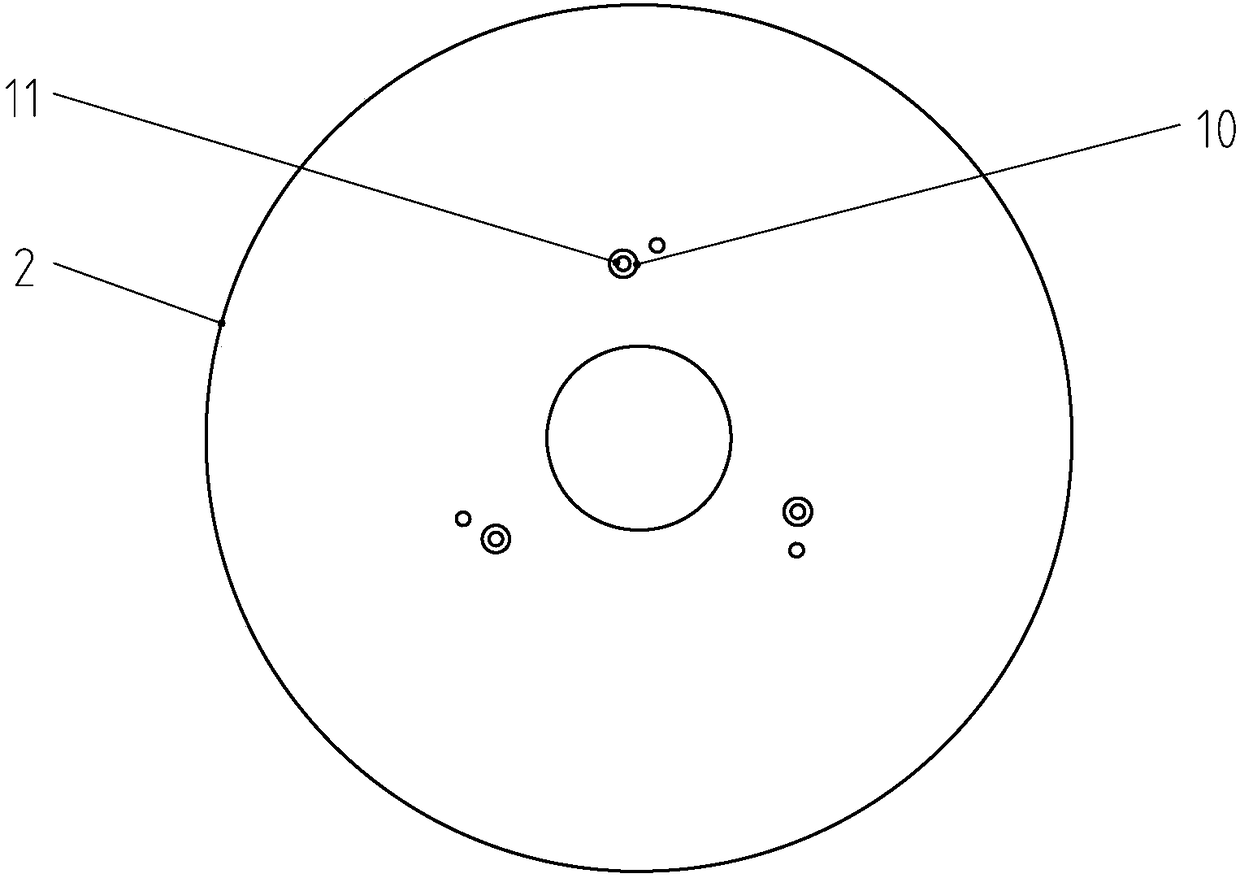
[0025] Such as figure 1 A centrifugal microfluidic chip shown includes a substrate 1 and a cover sheet 2 tightly fitted with the substrate. Both the substrate and the cover sheet are circular, the thickness of the substrate is 3mm, and the thickness of the cover sheet is 1mm. The center of the centrifugal microfluidic chip is There is a central through hole 3, and the central through hole runs through the substrate and the cover sheet. Such as figure 2 As shown, there are 21 circumferentially distributed reaction holes 4 and 3 circumferentially distributed main channels 5 connecting the reaction holes on the end surface of the base plate and the cover sheet, and each main channel is connected to 7 reaction holes. The volume of each reaction well is 25 μL, and the volume of the main channel between every two adjacent reaction wells is twice the volume of each reaction well. Before using the centrifugal microfluidic chip, different reaction wells can be preloaded with substan...


PUM

PropertyMeasurementUnit
Depthaaaaaaaaaa
Large hole diameteraaaaaaaaaa
Diameteraaaaaaaaaa

Abstract

The invention provides a centrifugal type micro-fluidic chip which is simple and reasonable in structure and saved in processing cost. The centrifugal type micro-fluidic chip comprises a substrate anda cover plate closely matched with the substrate, wherein the end surface of the substrate matched with the cover plate is provided with a plurality of reaction holes distributed in a circumferentialdirection and at least one main channel distributed in the circumferential direction and communicated with the plurality of reaction holes; each main channel is a wavy channel with a plurality of wave crests and a plurality of wave troughs; each reaction hole is provided with a connecting channel facing towards the center of the substrate; the connecting channels are communicated with the wave troughs of the main channels; the reaction holes are communicated with the main channels through the connecting channels; and the main channel between every two adjacent reaction holes is provided witha liquid sealing unit. The centrifugal type micro-fluidic chip provided by the invention has the advantages that based on the liquid sealing principle of a U-shaped tube, the reaction holes after centrifugal distribution are ensured to be full of liquid, reaction products in all reaction holes are prevented from diffusing into the adjacent reaction holes, the flow speed of the liquid in the main channels is uniform, and more uniform distribution of samples is realized.

Description

technical field [0001] The invention relates to a microfluidic chip, in particular to a centrifugal microfluidic chip, belonging to the fields of life science and medical detection. Background technique [0002] Microfluidic chip technology integrates the basic operation units of sample preparation, reaction, separation, and detection in the process of biological, chemical, and medical analysis into a micron-scale chip, and automatically completes the entire analysis process. Due to its great potential in the fields of biology, chemistry, and medicine, it has developed into a new research field interdisciplinary in biology, chemistry, medicine, fluid, electronics, materials, and machinery. Microfluidic chip technology provides a variety of implementation platforms for single-molecule nucleic acid detection methods. The analysis of biochemical samples is integrated on a microfluidic chip of several square centimeters through micromachining technology. Using a small centrifug...

Claims


Application Information

Patent Timeline
IPC IPC(8): B01L3/00
CPCB01L3/50273B01L2200/10B01L2300/0861B01L2400/0409
Inventor 黄宝福章喜超尹志嘉
Owner 杭州殷欣病理诊断中心有限公司
Why Eureka
Try Eureka