Vacuum tower for waste lubricating oil pretreatment

A technology of waste lubricating oil and decompression tower, which is used in lubricating oil distillation, processing of hydrocarbon oil, petroleum industry, etc., can solve the problems of decreased mass transfer and heat transfer efficiency, high temperature of waste oil at the outlet, and easy coking of tray equipment. To achieve the effect of reducing pressure drop, good separation effect and preventing coking blockage

Pending Publication Date: 2018-07-06
深圳至诚环境科技有限公司
View PDF11 Cites 1 Cited by
  • Summary
  • Abstract
  • Description
  • Claims
  • Application Information

AI Technical Summary

Problems solved by technology

[0009] In order to solve the existing waste lubricating oil pretreatment equipment, especially the use of trays and packing in the refining equipment, the mass transfer heat transfer efficiency is reduced, the pressure drop is too large, and the temperature of the waste oil at the outlet is high. In particular, it is necessary to solve the problems caused by the use of The problem of easy coking everywhere in the tray equipment caused by the tray
The technical solution of the present invention solves one or more problems to be solved or improved above

Method used


Image

  • Vacuum tower for waste lubricating oil pretreatment
  • Vacuum tower for waste lubricating oil pretreatment
  • Vacuum tower for waste lubricating oil pretreatment

Examples


Embodiment 1

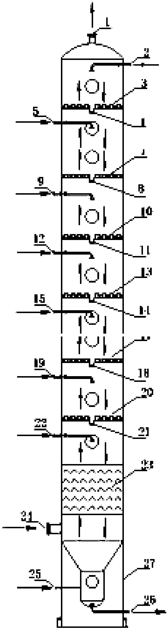
[0051] The structure of the present embodiment decompression tower is as figure 1 , in this embodiment, after the waste oil entering the feed port is vaporized, it passes through the over-vaporized oil production section, the distillate oil production section, and the diesel oil production section in sequence. In this embodiment, no filler is used, and the refined The distillation part and the rectification section only adopt the shower structure to carry out the rectification process.

[0052] The specific operation process is as follows:

[0053] The waste lubricating oil is heated in the heating furnace (the heating furnace is not shown), and the waste lubricating oil heated by the heating furnace enters the decompression tower through a mixer arranged between the heating furnace and the decompression tower.

[0054] Install the high-temperature mixer behind the heating furnace and on the pipeline before the vacuum tower feed, so that the raw material waste lubricating oil...

Embodiment 2

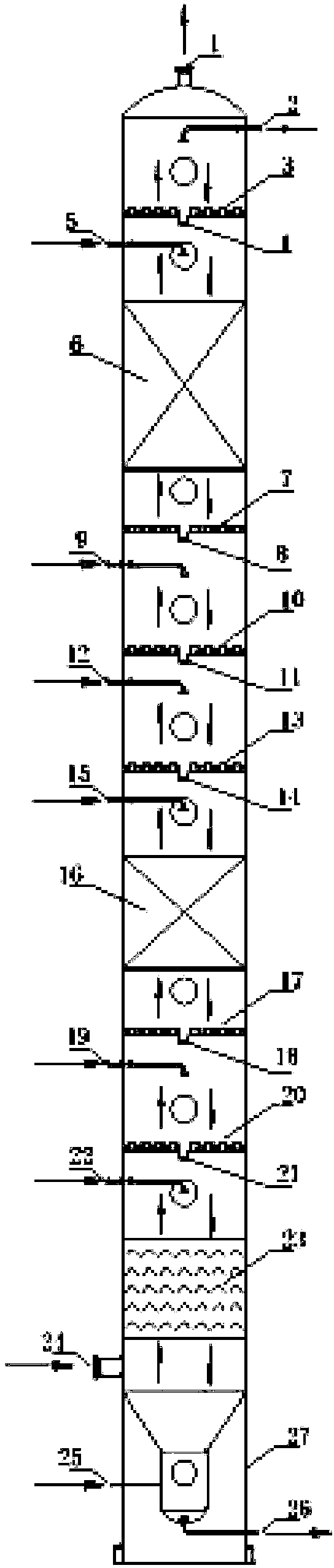
[0065] In this embodiment, after the waste oil entering the feed port is vaporized, it passes through the over-vaporized oil extraction section in sequence, and includes the first packing section, the distillate oil extraction section, the second packing section, and the diesel oil extraction section. . For details, please refer to figure 2 .

[0066] After setting the packing section, this embodiment still adopts the structure of 4 production sections (four side lines). In the structure of each extraction section, the over-vaporized oil extraction section includes an over-vaporized oil extraction port (21) and an over-evaporated oil return port (22), wherein the vaporized oil extraction port (21) is connected to an oil collection tank. And, wherein the diesel oil extraction section includes a first middle section, and the distillate oil extraction section includes a second middle section, a third middle section and a fourth middle section; each of the above four middle sec...

Embodiment 3

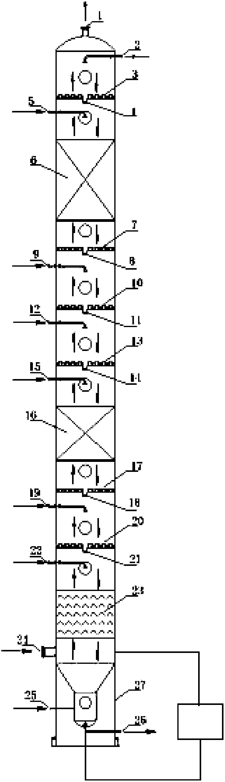
[0071] In this embodiment, after the waste oil entering the feed port is vaporized, it sequentially passes through the overvaporized oil extraction section, the first packing section, the distillate oil extraction section, the second packing section, and the diesel oil extraction section. The feature of this embodiment is that a tower bottom reboiler (using an electric heater structure) is provided to speed up the vaporization of waste lubricating oil, which sends a part of the tower bottom oil directly to the vicinity of the baffle after boiling to speed up vaporization.

[0072] The specific operating process is similar to that of Embodiments 1 and 2, so there is no need to repeat them here.

[0073] Here, the present invention firstly finds in the pretreatment and refining process of waste lubricating oil that high vacuum and low pressure drop are adopted in the decompression tower, and six sets of specially designed reflux liquid sprayers are arranged to fully disperse the ...


PUM

PropertyMeasurementUnit
diameteraaaaaaaaaa
viscosity indexaaaaaaaaaa

Abstract

The invention provides a vacuum tower for waste lubricating oil pretreatment. The vacuum tower is of a cylinder vertical structure; a tower tray is not arranged in the vacuum tower; a tower skirt, a feeding port, a baffle, an over-vaporized oil production section, a distillate oil production section, a diesel production section and a gas outlet are formed in the vacuum tower; two packing sectionscan be arranged among the diesel production section, the distillate oil production section and the over-vaporized oil production section according to the difficulty of separation of distillate oil ineach of the production sections; further, backflow spray distributors are respectively arranged on the three oil production sections and the packing sections. According to the vacuum tower in the scheme of the invention, the tower tray and fillers are directly replaced by utilizing a sprayer, the pressure drop is reduced in a manner of spray fractionation, the separation effect is good, and the process is simple, convenient and practical; moreover, according to the fraction separation difficulty, whether the fillers are provided or not can be freely selected, the heat and mass transfer efficiency is enhanced, and flexible and variable effects are realized, Importantly, the technical scheme of the invention solves the problem of influence on continuous production due to coking in all positions in the vacuum tower.

Description

technical field [0001] The invention relates to a device for separating, purifying and refining waste oil, in particular to a decompression tower for pretreatment of waste lubricating oil. Background technique [0002] In industrial production and use, lubricating oil is subjected to oxidation, thermal decomposition and impurity pollution in various machinery and equipment, and its physical and chemical properties reach the respective oil change indicators. The replaced oil is collectively called waste lubricating oil. Therefore, waste lubricating oil belongs to hazardous waste that is scrapped, polluted, high-temperature oxidized and has lost its original properties; on the other hand, waste lubricating oil is also a class of waste mineral oil with high utilization value. How to effectively pretreat this kind of waste oil with complex components to meet the requirements of industrial production is the focus of attention in the development of waste oil treatment technology. ...

Claims


Application Information

Patent Timeline
Patent Type & Authority Applications(China)
IPC IPC(8): C10G7/00
CPCC10G7/003C10G2300/202
Inventor 李义张长茂张巨龙刘彦昌
Owner 深圳至诚环境科技有限公司
Why Eureka
Try Eureka