Fluid end of culvert body and pump body and machine body series combined structure

A liquid end and pump body technology, which is applied to the components of pumping devices for elastic fluids, liquid fuel engines, pump components, etc. and other problems to achieve the effect of improving pump efficiency, prolonging life, and reducing vibration and noise.

Pending Publication Date: 2018-07-13
NINGBO HELI MECHANICAL PUMP CO LTD
View PDF0 Cites 5 Cited by
  • Summary
  • Abstract
  • Description
  • Claims
  • Application Information

AI Technical Summary

Problems solved by technology

[0005] The technical problem to be solved by the present invention is to solve the traditional reciprocating plunger pump with large consumables, large processing volume, easy stress concentration, low efficiency, short life of wearing parts, difficult disassembly and assembly, and easy cracking of the pump body under high pressure. Insufficient, and provide a fluid end of a series combination structure of the box body, the pump body, and the fuselage. It adopts the integrated design of the box body and the inlet valve to shorten the length of the pump body, simplify the accessories, reduce the dead volume, Improve pump efficiency, save costs, and meet lightweight design requirements

Method used


Image

  • Fluid end of culvert body and pump body and machine body series combined structure
  • Fluid end of culvert body and pump body and machine body series combined structure
  • Fluid end of culvert body and pump body and machine body series combined structure

Examples


Embodiment Construction

[0028] The present invention will be further described in detail below in conjunction with the accompanying drawings and embodiments.

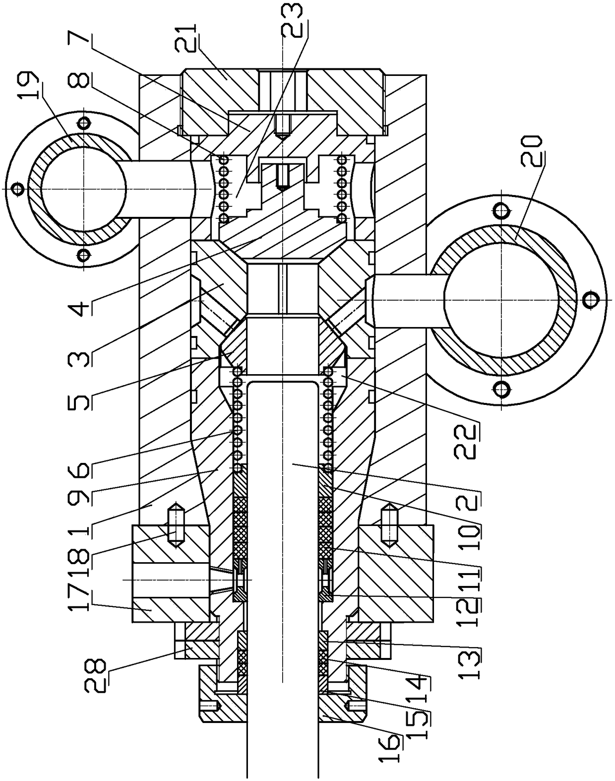
[0029] combine figure 1 As shown, the hydraulic end of the series combined structure of the body, the pump body and the fuselage of the present invention mainly includes a fuselage, a pump body 1, a plunger 2, a body 9, a sealing assembly, a combined valve, and a drain valve Set 7, spell cap 28 and cock 21, etc., wherein:

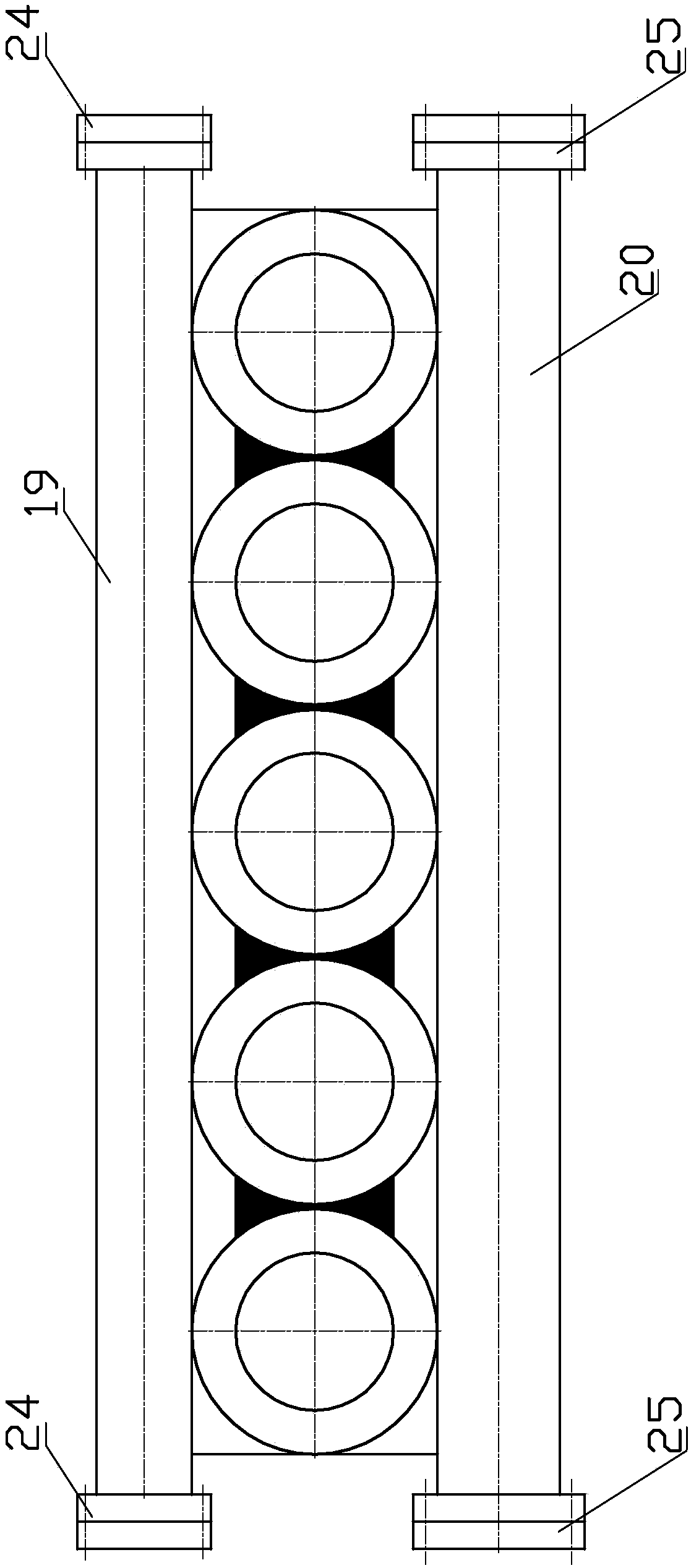
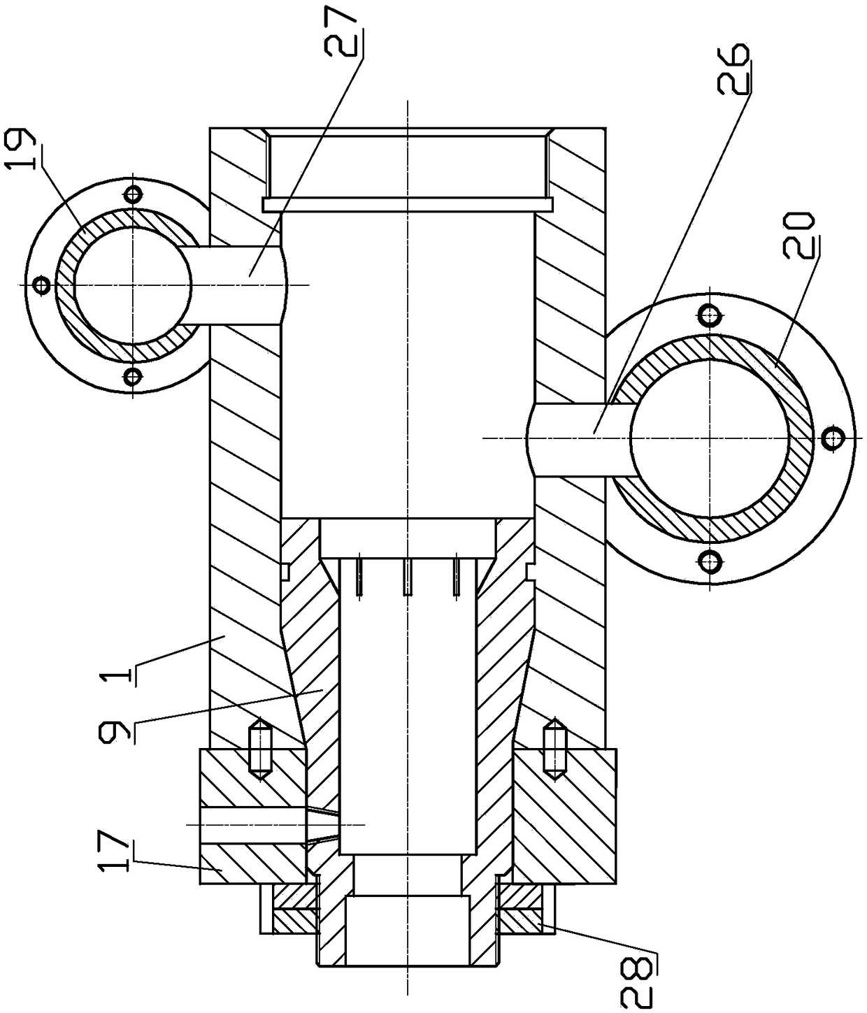
[0030] pump body 1 such as figure 2 As shown, it is configured according to the number of cylinders, which can be two cylinders, three cylinders, five cylinders, seven cylinders, nine cylinders, etc. The pump body 1 is assembled and welded with thick-walled profile pipes to form an "8" shape, and the upper end is at the drain port The discharge manifold 19 is assembled and welded at 27 places, and the liquid inlet manifold 20 is assembled and welded at the liquid inlet 26 at the lower end. After assembly and welding, th...


PUM


Abstract

The invention discloses a fluid end of a culvert body and pump body and machine body series combined structure. The fluid end is characterized in that a culvert body of the fluid end is located in aninner cavity of a pump body by a conical surface; male threads are formed in the tail end of the culvert body; the pump body is fixed to a machine body stand plate through a splicing cap connected tothe male threads; a combined valve comprises a valve seat provided with a front valve face and a rear valve face, the valve seat is arranged in the inner cavity of the pump body and is bonded with theend face of the culvert body for forming a working cavity; a liquid inlet valve core is arranged on the rear valve face of the valve seat; a liquid inlet spring and a self-sealing adjusting spring ofa filling are integrated; and a draining valve core and a draining spring are arranged on the front valve face of the valve seat. The fluid end adopts culvert body and liquid inlet valve integrated design, so that the length of the pump body is reduced, parts and components are simplified, the useless volume is reduced, the pump efficiency is improved, the cost is reduced, and the lightweight design requirement is met.

Description

technical field [0001] The invention relates to a hydraulic end of a reciprocating plunger pump, more specifically to a hydraulic end of a series combination structure of a box body, a pump body and a fuselage. Background technique [0002] The main components of the reciprocating plunger pump are the power end and the fluid end. , box body, plunger, packing, guide sleeve, regulator, compensation spring, inlet valve group, liquid discharge valve group, valve sleeve, gland, flange high-pressure bolts, etc. The hydraulic end is mainly responsible for the medium liquid, and the plunger of the liquid end drives the plunger to reciprocate to do work under the power end, so that the medium liquid is discharged after a certain amount of boosting, which meets the requirements of the working condition. [0003] Since the reciprocating plunger pump is a volumetric high-pressure pump, it has been widely used in various industrial fields for conveying high-pressure liquids. The fluid e...

Claims


Application Information

Patent Timeline
Patent Type & Authority Applications(China)
IPC IPC(8): F04B53/16F04B53/10F04B53/22
CPCF04B53/1092F04B53/16F04B53/22
Inventor 陈明海陈英峰
Owner NINGBO HELI MECHANICAL PUMP CO LTD
Why Eureka
Try Eureka