Low-frequency magnetite material unit structure and its combination device

A technology of unit structure and special materials, applied in circuit devices, electrical components, inductors, etc., can solve the problem of low power level and achieve the effect of wide tuning range

Active Publication Date: 2021-03-16
TONGJI UNIV
View PDF5 Cites 0 Cited by
  • Summary
  • Abstract
  • Description
  • Claims
  • Application Information

AI Technical Summary

Problems solved by technology

[0006] In view of the above situation, the present invention provides a low-frequency magnetite material unit structure and its combination device, which solves the problem of the existing magnetite material application by adopting multiple windings of metal wires and combining with lumped parameter electronic components. It can support the technical problem that the power level is not high at the time, and realize the purpose of applying the magnetic material to the high-power and low-frequency wireless power transmission of more than 100 watts

Method used


Image

  • Low-frequency magnetite material unit structure and its combination device
  • Low-frequency magnetite material unit structure and its combination device
  • Low-frequency magnetite material unit structure and its combination device

Examples


Embodiment 1

[0046] Embodiment 1: A magnetic material unit structure.

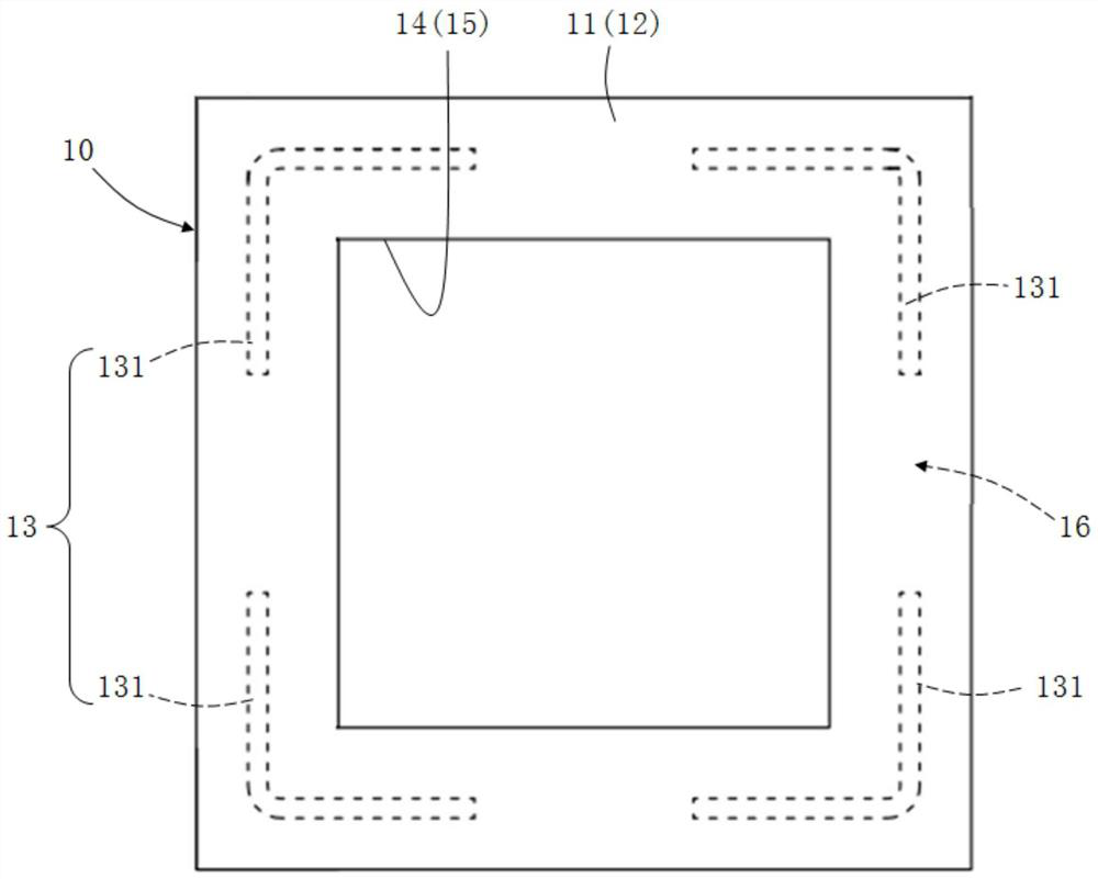
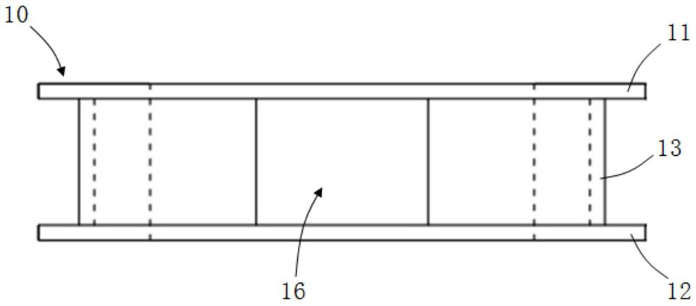
[0047] A magnetic material unit structure that can be used for wireless energy transmission of high-power electric vehicles at a working frequency of 85KHz, which is composed of a plexiglass plate (insulating medium plate 10), a litz wire (metal wire 20) and a capacitor (lumped parameter electronic components).

[0048] The main steps for the preparation of the unit structure of the magnetite material include:

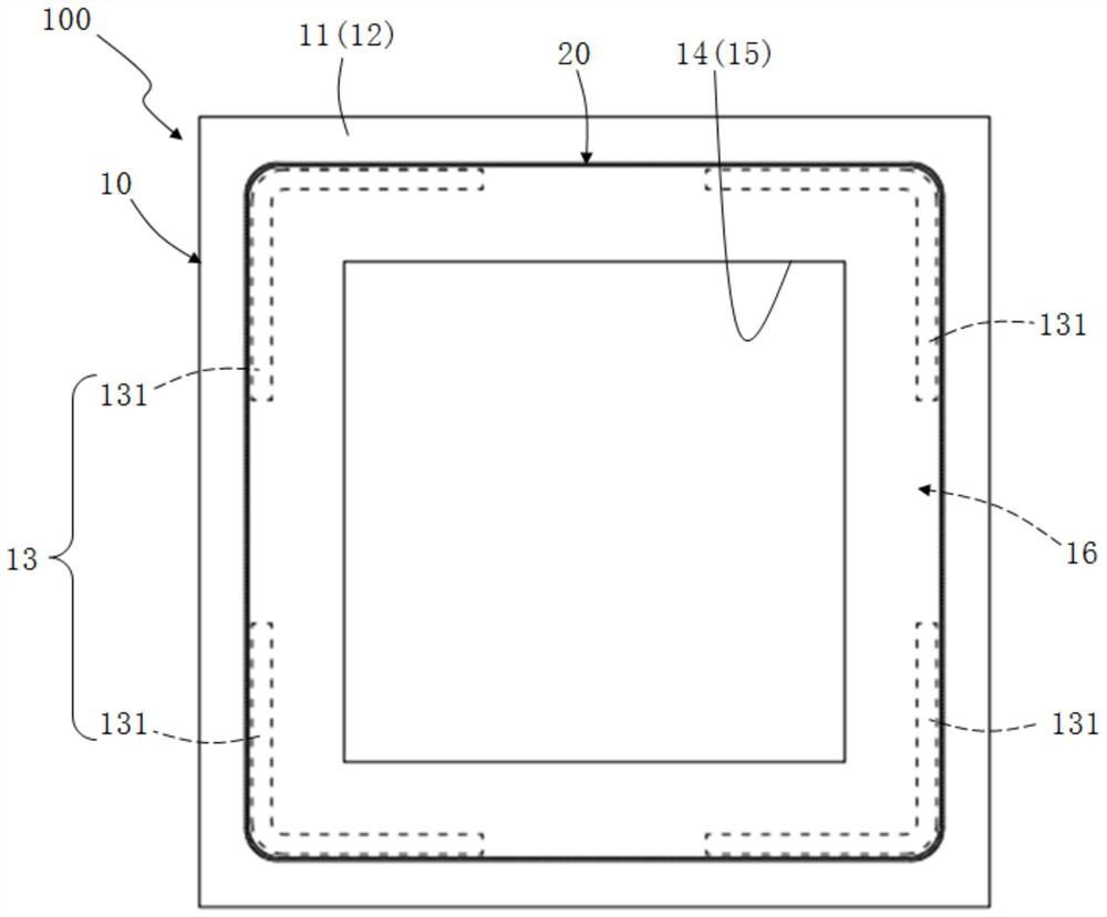
[0049] The Litz wire was used to perform multiple dense windings on the side of the plexiglass plate, and 79 turns were wound, and then capacitors were welded at the head and tail ends of the Litz wire.

[0050] Among them, the plexiglass plate structure used in the magnetic material unit structure 100 of the present invention is as follows: figure 1 As shown, the material is polymethyl methacrylate (PMMA). The geometric parameters of this plexiglass plate are as follows: the length of the plate is 120mm, th...

Embodiment 2

[0053] Embodiment 2: A magnetite material unit structure assembly device composed of the magnetite material unit structure in embodiment 1.

[0054] A low-frequency magnetite overall material that can be used for wireless power transmission of high-power electric vehicles at a working frequency of 85KHz. like Figure 5 , Image 6 , showing a 5×5 array of low-frequency magnetite material unit structure combination devices formed by periodically replicating 25 magnetite material unit structures in Example 1 on a two-dimensional plane; wherein, the low-frequency magnetic The total length and total width of the Meteor material unit structure combination device are both 600mm, and the total thickness is 31mm.

[0055] like Figure 7 As shown, it shows the change of the effective magnetic permeability measured by the low-frequency magnetic material unit structure combination device of the present invention with frequency. Depend on Figure 7 It can be seen that the experimental...


PUM

PropertyMeasurementUnit
diameteraaaaaaaaaa
areaaaaaaaaaaa
lengthaaaaaaaaaa

Abstract

The invention provides a low-frequency magnetic metamaterial unit structure body and a combination device thereof. By means of a process of winding multiple turns of metal wires and combining with lumped-parameter electronic elements, the magnetic metamaterial unit structure body is formed in a sub-wavelength wavelength size so that the magnetic metamaterial unit structure body can be subjected toresonance by loading the resonance frequency of the lumped-parameter electronic elements under cooperation with the metal wires with equivalent magnetic conductivity. The low-frequency magnetic metamaterial unit structure body and the combination device thereof solve the technical problem that the supportable power level of existing metamaterials is not high during application and achieve the purpose of applying the metamaterials in wireless power transmission with low frequency and high power more than 100 watts.

Description

technical field [0001] The present invention relates to the technical field of wireless power transmission, in particular to a low-frequency magnetic material unit structure and a combined device thereof for high-power wireless power transmission. Background technique [0002] In recent years, the technology of wireless power transmission has been continuously developed and promoted in the fields of portable mobile devices and electric vehicles. However, some practical problems encountered in this process require more precise regulation of the electromagnetic near-field. For example, a stable and uniform large-area magnetic field needs to be provided during the wireless charging of smartphones to improve energy transmission efficiency. [0003] In this regard, there are still some problems with the traditional coils wound with copper wires: on the one hand, although the technology of winding multi-turn coils on the market is very mature, the coil structure is relatively sim...

Claims


Application Information

Patent Timeline
Patent Type & Authority Patents(China)
IPC IPC(8): H01F38/14H01F5/00H01F5/06H02J50/12
CPCH01F5/00H01F5/06H01F38/14H02J50/12
Inventor 李云辉曾超李果王宇倩郭桂春俞维健方恺陈宇光张冶文陈鸿
Owner TONGJI UNIV
Why Eureka
Try Eureka