Novel air-cooled power cabinet

A power cabinet and air-cooling technology, applied in electrical components, substation/distribution device housing, substation/switch layout details, etc. Environmental protection function, realize the effect of air purification and convenient use

Active Publication Date: 2018-07-20
高原(山东)机电设备有限公司
View PDF8 Cites 3 Cited by
  • Summary
  • Abstract
  • Description
  • Claims
  • Application Information

AI Technical Summary

Problems solved by technology

[0003] In the existing technology, such as a semiconductor refrigeration dehumidification and cooling power cabinet disclosed in Chinese Patent Publication No. CN103872584A, it includes a power cabinet body and a semiconductor refrigeration sheet. Outside the cabinet, the cooling surface of the semiconductor refrigeration sheet is connected to the heat dissipation and dehumidification device, and the heat dissipation and dehumidification device is equipped with a water collecting pan, which leads out of the cabinet; since the cold surface made of the semiconductor refrigeration sheet is provided with an inclined channel, the air contacting the semiconductor refrigeration sheet is cooled Sinking, the low-temperature air descends along the lower end of the inclined channel and flows out from the lower end, generating negative pressure, so that the high-temperature air is replenished from the high end of the inclined channel, and the air outside the inclined channel falls in the cabinet. The low-temperature air descends and the high-temperature air rises; It is connected to the cooling surface of the semiconductor refrigeration sheet, the temperature of the heat dissipation and dehumidification device is low, the high temperature air in the cabinet is cooled by the heat dissipation and dehumidification device, the water vapor in the high temperature air condenses into water, adheres to the surface of the heat dissipation and dehumidification device and flows into the water collection tray, and the cooling efficiency is higher High, but the device has high energy consumption, which is not conducive to popularization and use
[0004] Another example is a convective heat dissipation power cabinet disclosed in Chinese Patent Publication No. CN105186326A, which includes a cabinet body and a cabinet door. self-tapping screw, the self-tapping screw is threadedly connected with the side plate, the self-tapping screw is embedded in the upper cover and the lower cover, and a conductive cloth gasket is arranged between the upper cover, the lower cover and the side plate, The upper cover is provided with a blower, the lower cover is hollow, the lower cover is equipped with an exhaust fan, the exhaust fan is embedded in the lower cover, and the lower cover is provided with an exhaust hole. An aluminum veneer is arranged on the side plate, a ventilation hole is arranged on the aluminum veneer, a magnet is installed on the aluminum veneer, a heat dissipation louver is arranged on the side plate, and a vacuum suction cup is installed on the cabinet door , the vacuum chuck is provided with a thermometer, and the thermometer is embedded in the vacuum chuck; the convection heat dissipation power cabinet has a good heat dissipation effect, but the function of the device is single

Method used


Image

  • Novel air-cooled power cabinet
  • Novel air-cooled power cabinet
  • Novel air-cooled power cabinet

Examples


Embodiment Construction

[0033] The technical solution of the present invention will be further described in detail below in conjunction with the accompanying drawings, but the protection scope of the present invention is not limited to the following description.

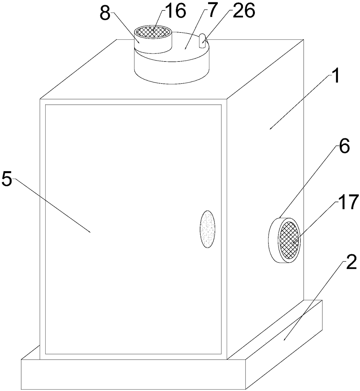
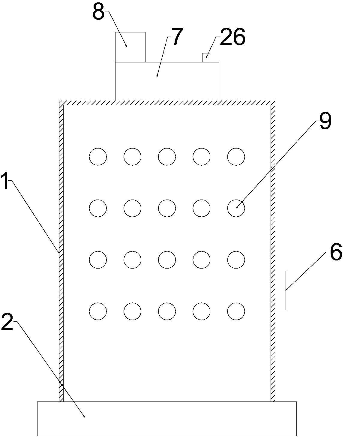
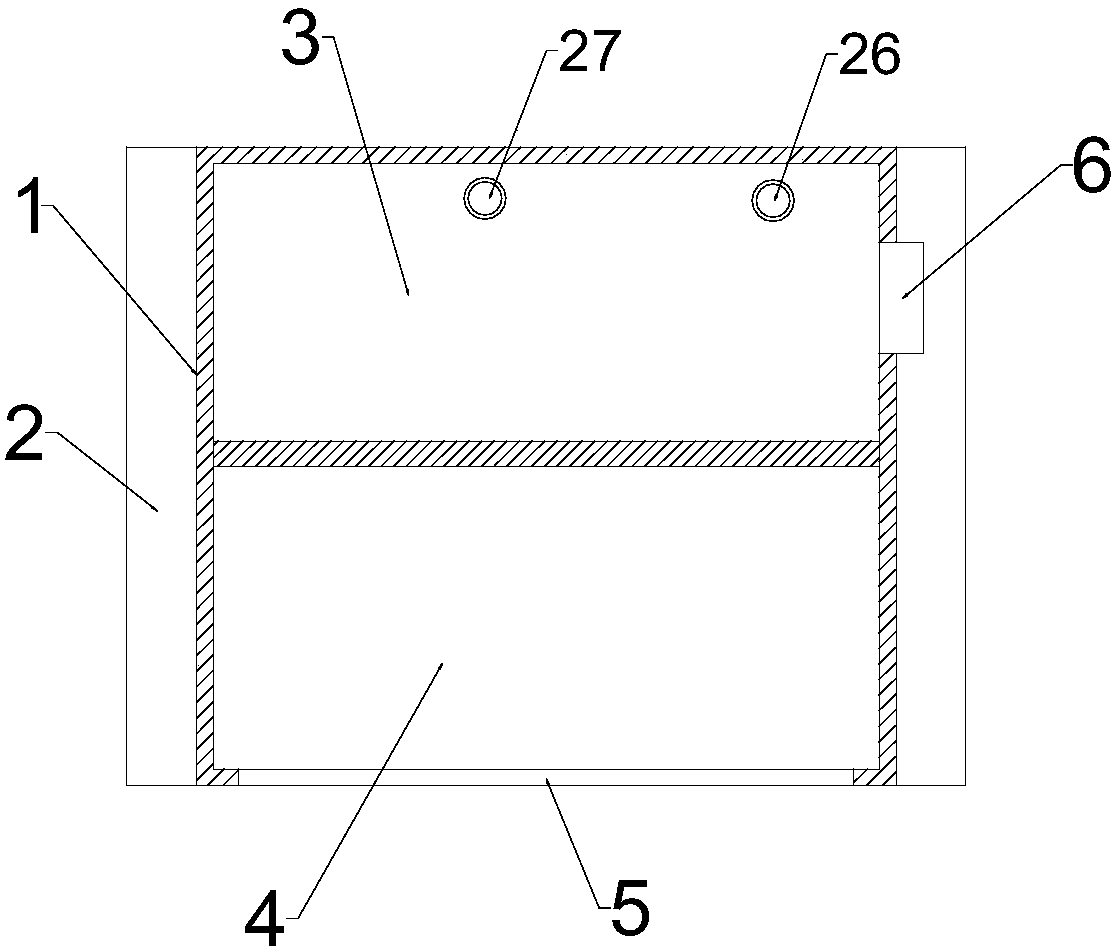
[0034] Such as Figure 1 to Figure 6 As shown, a new type of air-cooled power cabinet includes a cabinet body 1, a bottom box 2 and an air-cooling mechanism. A first partition is arranged inside the body 1, and the first partition divides the cabinet body into an operation room 4 and a component room 3 arranged side by side, and a plurality of installation holes 9 are uniformly arranged on the first partition, so that The installation hole 9 is used to install the instrument or control switch of the electrical component, the component room 3 is used to place the cable of the electrical component, the side wall of the cabinet body 1 is also provided with an air inlet 6, and the air-cooled The mechanism includes a top box 7, a blower fan 10 ...


PUM


Abstract

The invention relates to the technical field of electrical equipment and particularly relates to a novel air-cooled power cabinet comprising a cabinet body, a bottom box and an air cooling mechanism.The cabinet body is arranged on the top of the bottom box, and a cabinet door is arranged on a side wall of the cabinet body. An operating room and a component room are arranged in the cabinet body, and a plurality of mounting holes is evenly arranged on a first partition plate. An air inlet is further arranged on the side wall of the cabinet body. The air cooling mechanism includes a top box, a fan, and an air outlet pipe. The top box and the air outlet pipe are arranged at the top of the cabinet separately, and the air outlet pipe passes through the top box to communicate with the componentroom. The fan is arranged in the air outlet pipe, the top port of the air outlet pipe is provided with a first filter mesh, and a fine filter mesh and a coarse filter mesh are orderly arranged in theair outlet pipe from the top to bottom. The novel air-cooled power cabinet of the invention has the advantages of a simple structure and convenience in use, air cooling and heat dissipation can be achieved, air purification is effectively achieved in an air cooling process, and the environmental protection function of a device is improved.

Description

technical field [0001] The invention relates to the technical field of electrical equipment, in particular to a novel air-cooled power cabinet. Background technique [0002] The power system is a power production and consumption system composed of power generation, power transformation, power transmission, power distribution and power consumption. Its function is to convert the natural primary energy into electrical energy through the power generation device, and then supply the electrical energy to each load center through the power transmission and distribution system, and then convert it into different forms such as power, heat, and light through various equipment. energy to serve the regional economy and people's lives. The power cabinet is a commonly used power infrastructure, which is equipped with a large number of power components. When the power cabinet is working, a large amount of heat will be generated inside. Therefore, in order to maintain the normal operation...

Claims


Application Information

Patent Timeline
Patent Type & Authority Applications(China)
IPC IPC(8): H02B1/56H02B1/28
CPCH02B1/28H02B1/565
Inventor 徐自强
Owner 高原(山东)机电设备有限公司
Why Eureka
Try Eureka