Ditching device suitable for wide-trench large-earthwork operation and ditching machine and loosener
A technology for earthwork operations and wide trenches, which is applied to agricultural machinery and tools, agriculture, and land preparation machinery, etc. It can solve the problems of increasing chain knife wear, consuming more power, and length of the whole machine.
- Summary
- Abstract
- Description
- Claims
- Application Information
AI Technical Summary
Problems solved by technology
Method used
Image
Examples
Embodiment 1
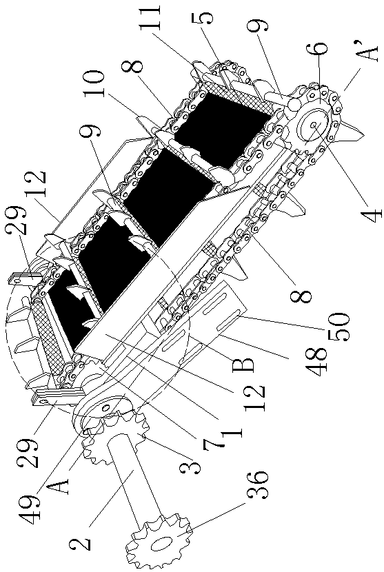
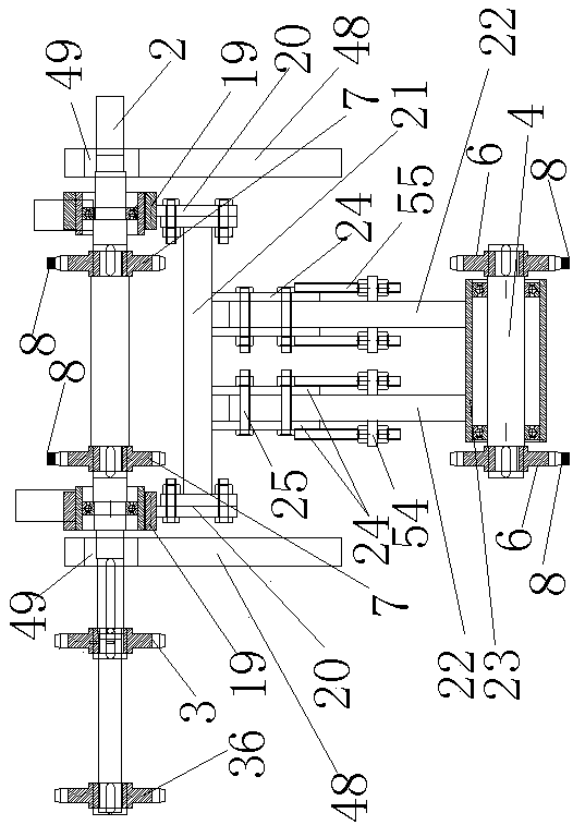
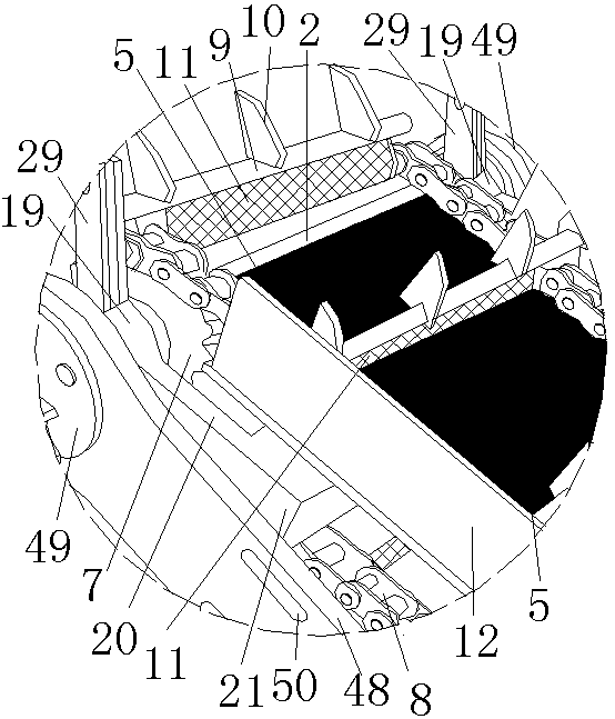
[0083] Example 1. like Figure 1 to Figure 3 As shown, the ditching device suitable for wide ditch and large earthwork operations is characterized in that: the ditching device includes a ditching device support 1, the rear end of the ditching device support 1 is provided with a drive rotation horizontal shaft 2, and the ditching device support The front end of 1 is provided with driven rotation horizontal shaft 4, and the top surface of ditching device support 1 is provided with panel 5; The chain is provided with the main driving wheel 7 of the chain directly behind the driving wheel 6, and each chain is connected to each other from the driving wheel 6 and the main driving wheel 7 of the chain directly behind it by an annular transmission chain 8; The cross bar 9 is connected with a ditching tool 10 on the cross bar 9 .
[0084] A scraper 11 is provided on the side of the connecting bar 9 close to the ditching device bracket 1, and the scraper 11 is located between the two ...
Embodiment 2
[0090] Example 2. like Figure 4 , Figure 5 Shown, a scarifier. The scarifier includes a traveling mechanism 26 and a power transmission system installed on the traveling mechanism 26, the ditching device described in Embodiment 1, and a ditching control device that can make the ditching device rotate along the central axis of the driving and rotating horizontal shaft 2. system, the driving and rotating horizontal axis 2 of the ditching device is perpendicular to the connection line between the head and tail of the traveling mechanism 26; when working, the driving and rotating horizontal axis 2 is located at the upper rear of the driven rotating horizontal axis 4; , the driving rotation horizontal shaft 2 is located directly behind the driven rotation horizontal shaft 4; the ditching control system includes a control device bracket 28 located on the traveling mechanism 26, and a retractable device is hinged on the control device bracket 28, and the retractable device is con...
Embodiment 3
[0096] Example 3. like Figure 10 , Figure 11 As shown, the difference between this embodiment and Embodiment 2 is that the retractable device is a hydraulic cylinder 27 whose output shaft is perpendicular to the central axis of the driving and rotating horizontal shaft 2, and two driving and rotating horizontal shaft sleeves 19 or two vertical plates Respectively be provided with riser 29 on 20, be connected with connecting cross bar 16 between two risers 29, the output shaft of hydraulic oil cylinder 27 is hinged with connecting rod 16.
PUM
 Abstract
Description
Claims
Application Information
 - R&D
- Intellectual Property
- Life Sciences
- Materials
- Tech Scout
- Unparalleled Data Quality
- Higher Quality Content
- 60% Fewer Hallucinations
Browse by: Latest US Patents, China's latest patents, Technical Efficacy Thesaurus, Application Domain, Technology Topic, Popular Technical Reports.
© 2025 PatSnap. All rights reserved.Legal|Privacy policy|Modern Slavery Act Transparency Statement|Sitemap|About US| Contact US: help@patsnap.com


