
Reinforced bar cutting device for engineering construction

A cutting device and engineering construction technology, applied in grinding/polishing safety devices, manufacturing tools, metal processing equipment, etc., can solve the problems of debris affecting air quality, handling scratches, work difficulties, etc. The effect of avoiding air pollution and having a high degree of integration

Inactive Publication Date: 2018-07-24
NANJING CHUQING ELECTRONICS TECH CO LTD
View PDF0 Cites 6 Cited by
  • Summary
  • Abstract
  • Description
  • Claims
  • Application Information

AI Technical Summary

Problems solved by technology

[0003] At present, there are generally automatic steel bar cutting machines and semi-automatic steel bar cutting machines on the market. The fixed-length cutting of steel bars is realized by blades, which is especially widely used in engineering. However, due to the sharp ends of the steel bars after cutting, It is easy to cause scratches during transportation, which brings difficulties to the work; and when grinding the end of the steel bar, it is easy to cause debris to affect the air quality, and the high temperature generated will also accelerate the wear of the grinding wheel

Method used


Image

  • Reinforced bar cutting device for engineering construction
  • Reinforced bar cutting device for engineering construction
  • Reinforced bar cutting device for engineering construction

Examples


Embodiment Construction

[0021] The following will clearly and completely describe the technical solutions in the embodiments of the present invention with reference to the accompanying drawings in the embodiments of the present invention. Obviously, the described embodiments are only some, not all, embodiments of the present invention. Based on the embodiments of the present invention, all other embodiments obtained by persons of ordinary skill in the art without making creative efforts belong to the protection scope of the present invention.

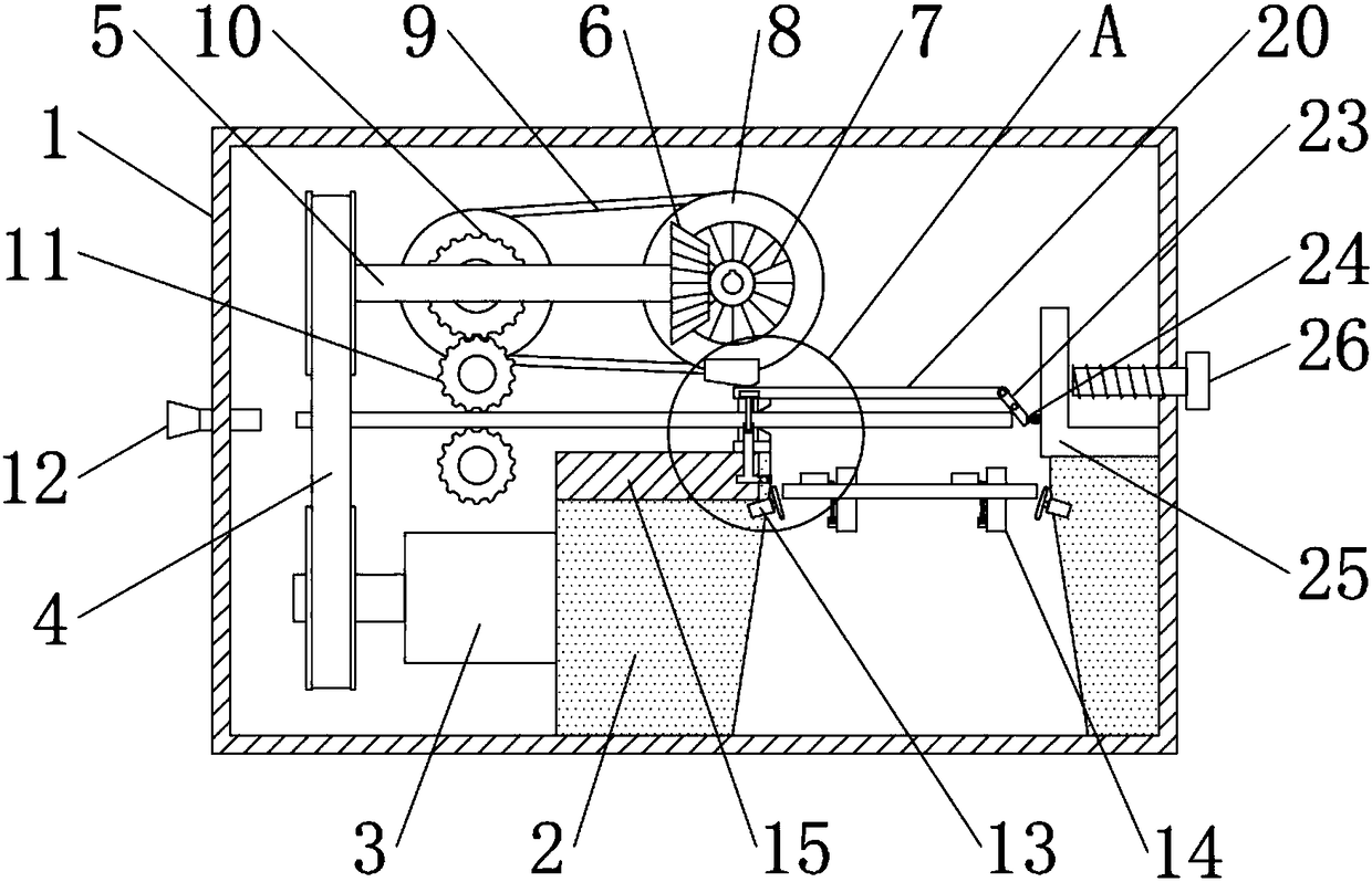
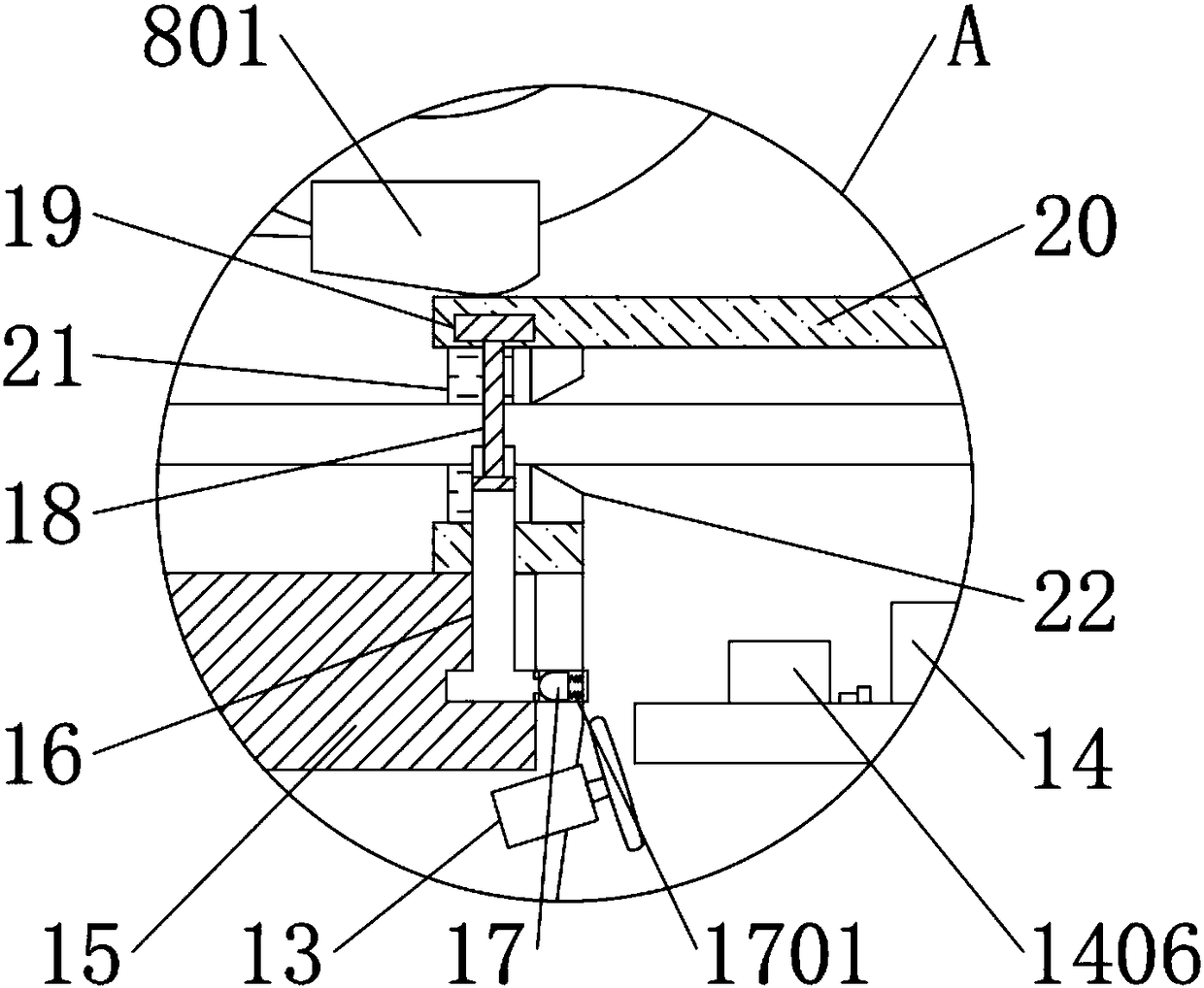
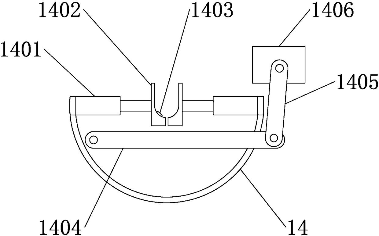
[0022] see Figure 1-4 A steel bar cutting device for engineering construction is shown, comprising a main body 1 and a housing 2 located at the bottom of the main body 1, a main motor 3 is fixedly installed on one side of the housing 2, and the output end surface of the main motor 3 is The first belt 4 is connected to the surface of one end of the horizontal shaft 5 through transmission, the other end of the horizontal shaft 5 is fixedly installed with a firs...


PUM


Abstract

The invention discloses a reinforced bar cutting device for engineering construction. The reinforced bar cutting device for engineering construction comprises a main body, a shell, a main motor, a first belt, a cross shaft, a first bevel gear, a second bevel gear, a driving wheel, a hammer, a second belt, a speed reducing gear, traction rollers, a guiding hole, a first motor, rotors, electric pushrods, clamping plates, a switch, a rotating bar, a connecting rod, a second motor, a water tank, a water pipe, a one-way plug, a first spring, a piston rod, a fixing block, straight bars, an elasticsheet, blades, a rotary rod, a second spring, a fixed-length plate and a screw rod. According to the reinforced bar cutting device for engineering construction, a reinforced bar is clamped through theclamping plates, so that two ends of the reinforced bar can be polished, the occurrence of the phenomenon that workers get hurt by sharpness of the end parts of the reinforced bar when carrying the reinforced bar is avoided, the carrying efficiency is improved, and the probability that the workers are scratched by the reinforced bar is reduced; and during the working of the blades, water is poured on a grinding wheel at the same time, so that the air pollution caused by chippings generated during polishing is avoided, the grinding wheel is conveniently cooled, the abrasion speed of the grinding wheel is reduced, and the service life is prolonged.

Description

technical field [0001] The invention relates to a cutting device, in particular to a steel bar cutting device for engineering construction, which belongs to the technical field of engineering machinery. Background technique [0002] Steel bar cutting machine is a tool used for cutting steel bars. It is one of the essential equipment for steel bar processing. It is mainly used for fixing steel bars in building construction, bridges, tunnels, power stations, large-scale water conservancy projects, etc. Compared with other cutting equipment, the steel bar cutting machine has the characteristics of light weight, less energy consumption, reliable work and high efficiency. Therefore, it has been widely used in mechanical processing and small rolling mills in recent years. It is widely used in various fields of national economic construction. played an important role. [0003] At present, there are generally automatic steel bar cutting machines and semi-automatic steel bar cutting...

Claims


Application Information

Patent Timeline
Patent Type & Authority Applications(China)
IPC IPC(8): B21F11/00B21F23/00B24B9/04B24B41/00B24B55/02
CPCB21F11/00B21F23/00B24B9/04B24B41/005B24B55/02
Inventor 丁洋洋
Owner NANJING CHUQING ELECTRONICS TECH CO LTD
Learn More