3D (Three Dimensional) printing machine with material recycling and planting cleaning device

A technology of 3D printer and cleaning device, which is used in processing and recycling, manufacturing auxiliary devices, 3D object support structure, etc., can solve problems such as inability to use, inconvenient to use, and complex structure.

Active Publication Date: 2018-07-24
HEFEI UNIV OF TECH
View PDF4 Cites 6 Cited by
  • Summary
  • Abstract
  • Description
  • Claims
  • Application Information

AI Technical Summary

Problems solved by technology

This material recovery device can only recover small pieces of waste, and the melt extrusion device is water-cooled, requiring a separ

Method used


Image

  • 3D (Three Dimensional) printing machine with material recycling and planting cleaning device
  • 3D (Three Dimensional) printing machine with material recycling and planting cleaning device
  • 3D (Three Dimensional) printing machine with material recycling and planting cleaning device

Examples


Embodiment 1

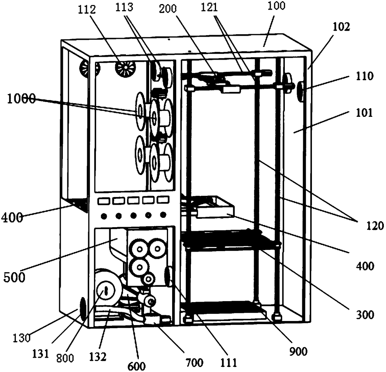
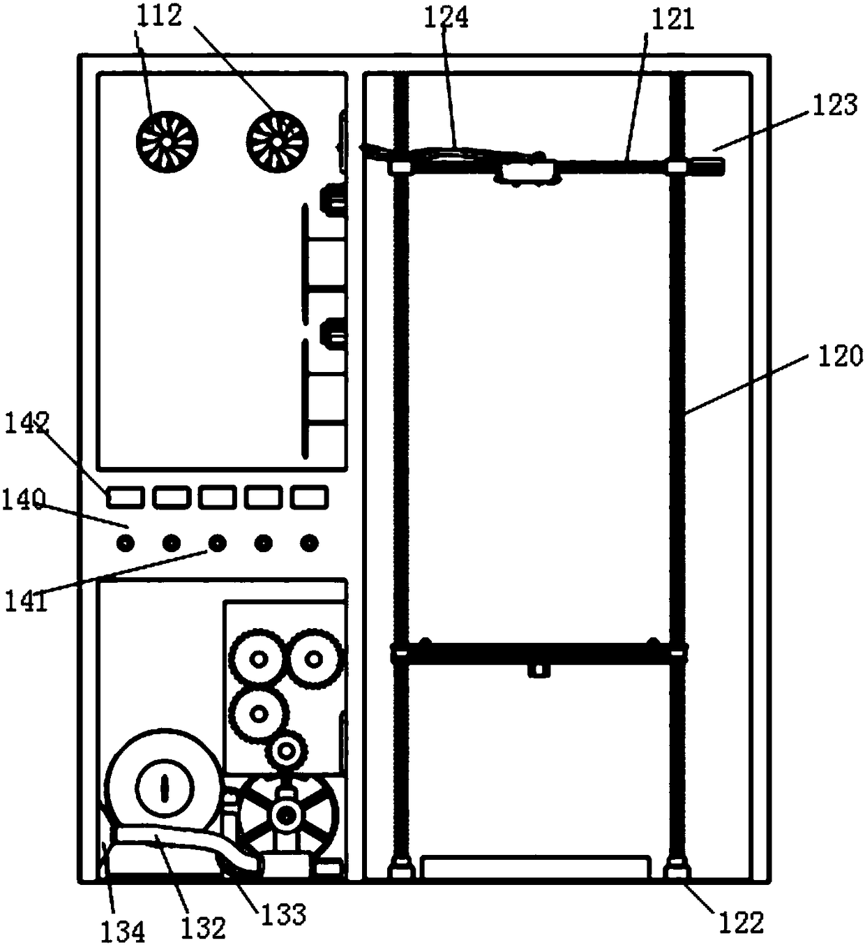
[0051] Example 1: Combining figure 1 and figure 2 See 3D printer main frame 100.

[0052]The printer main frame 100 includes a sheet metal shell 101, a support column 102, a fan (110-113), an internal structure ball screw 120, an air inlet 130, and a control panel 140. The sheet metal shell is fixed on the support column 102, and the right side of the printer is Fan 1 110 is installed on the sheet metal shell 101, fan 4 113 is installed on the upper part of the middle sheet metal shell 101, and fan 2 111 is installed on the lower part, and the fan 1 110, fan 2 111 and fan 4 113 work together to ensure the temperature of the molding chamber Stable; the rear sheet metal shell 101 is equipped with a fan 3 112 for dissipating the heat inside the printer; four ball screws 120 are installed in the main frame 100, the bottom of the ball screw 120 is provided with a mounting seat 122, and the upper part is installed with X direction ball screw 121, two stepping motors 123 are respe...

Embodiment 2

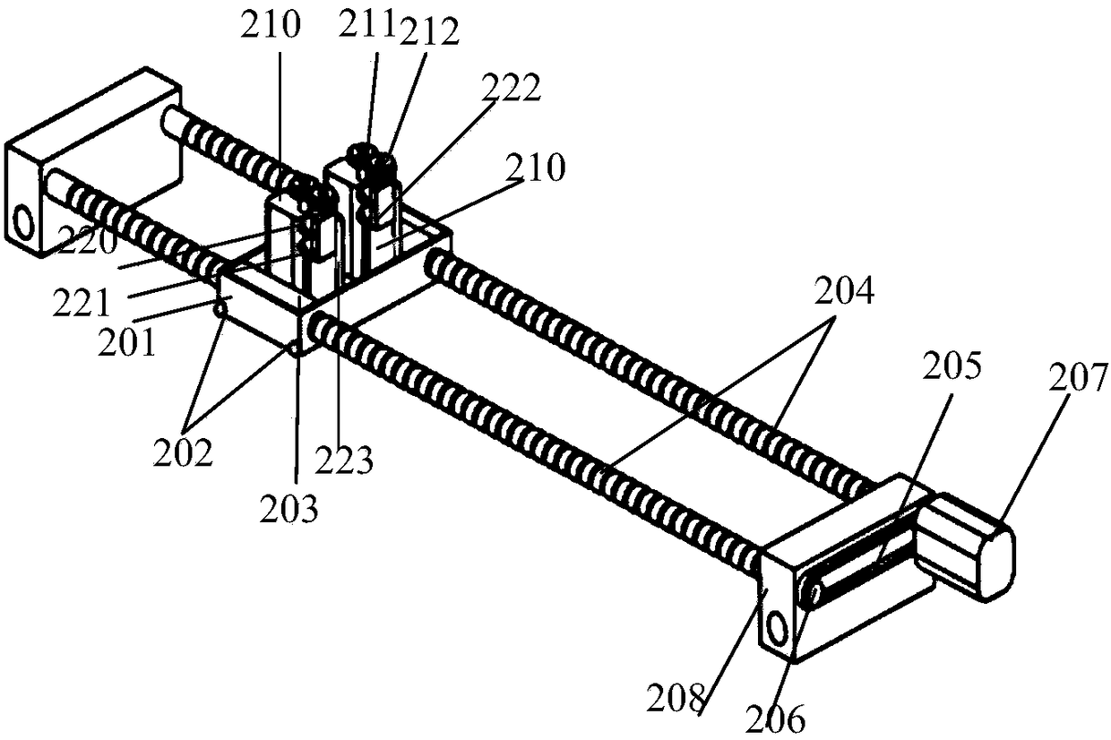
[0053] Embodiment 2: Combination image 3 , Figure 4 and Figure 5 See printing device 200 .

[0054] The printing device 200 includes a mounting frame 201, a ball screw thread 203, a DC motor 210, and a print head 224. Four temperature sensors 202 are installed at the four corners of the bottom of the mounting frame 201 to monitor the temperature of the printer forming chamber in real time. The mounting frame is provided with a ball screw thread. 203, and a Y-direction ball screw 204 is installed. In order to improve the accuracy of the synchronous movement of the ball screws, a timing belt 205 is used to connect two Y-direction ball screws 204, and a timing belt pulley 206 is provided. The timing belt pulley 206 is connected with the step The first motor 207 is connected, and the stepper motor 207 provides the power of the whole printing device. The Y-direction ball screw is equipped with a ball screw connection block 208, and the connection block 208 is connected with th...

Embodiment 3

[0055] Example Three: Combining Figure 6 and Figure 7 See print platform 300.

[0056] The printing platform 300 includes a slot-type printing plate 303 , a ball driver 310 and a stepping motor 2 320 . The four sides of the printing platform 300 are provided with temperature sensors 301, which are used to monitor the temperature of the molding chamber in real time. The surface of the printing platform 300 is provided with a groove-shaped printing plate 303. The printing nozzle 224 extrudes the fuse, and the fuse is formed on the printing plate 303, and Embedded in the groove, it helps the printed parts not to be deformed; the four corners of the printing platform 300 are provided with through holes 302, the ball screw 120 passes through the through holes 302, and four ball drivers (310-313) are installed under the through holes 302, The first ball driver 310 and the second ball driver 311 link to each other with the pulley driver 324 through the first synchronous belt 315;...


PUM


Abstract

The invention discloses a 3D (Three Dimensional) printing machine with a material recycling and planting cleaning device. The 3D printing machine is provided with a crushing device; a crushing rolleris provided with crushing teeth and can be used for crushing waste materials with a relatively great grain diameter; the 3D printing machine is provided with a smashing device, the smashing device isinternally provided with a spiral tapered saw tooth crushing cutter for effectively crushing the waste materials and conveying the waste materials into a melting cavity; a fuse wire strong-wind cooleris arranged and is used for effectively cooling a fuse wire and conveying the cooled wire into a wire winding device; the recycled waste materials can be directly collected and stored by the wire winding device and also can be directly used as raw materials of the printing machine to be input. The 3D printing machine is provided with double printing heads; a printing spraying nozzle adopts doublefeeding openings and each feeding opening is provided with an electronic control valve; the feeding openings can be automatically switched to realize rapid material exchange; a printing platform cleaning device is arranged and can be used for automatically cleaning a printing platform; the cleaned waste materials are directly conveyed into the crushing device and the printing efficiency is accelerated. By adopting the 3D printing machine disclosed by the invention, the recycling and reutilization of the 3D printing waste materials are realized, the utilization rate of the raw materials is improved and the material waste problem is effectively solved.

Description

technical field [0001] The invention relates to the technical field of 3D printers, in particular to a 3D printer with waste recycling and platform cleaning devices. Background technique [0002] 3D printer is a rapid prototyping device. Through slicing software, the three-dimensional model is converted into printing parameters, and materials such as plastic or metal powder are used to realize rapid and accurate prototyping of complex models, reducing the time required for product design and avoiding The increase in time and cost caused by repeated mold opening greatly shortens the product development cycle. This technology is being widely used in scientific research and daily life. [0003] At present, most of the existing 3D printers on the market are mainly small fused deposition types, and the raw materials used are mostly ABS, PLA, etc. During the printing process, usually due to parameters and environmental problems, the printed model does not meet the requirements, ...

Claims


Application Information

Patent Timeline
IPC IPC(8): B29C64/35B29C64/357B29C64/393B29C64/364B33Y40/00B33Y50/02
CPCB33Y40/00B33Y50/02
Inventor 张雷钟言久郑雨李杰阚欢迎郑辰兴赵希坤
Owner HEFEI UNIV OF TECH
Why Eureka
Try Eureka