Connecting device and connecting structure of steel bars and mounting method of connecting structure

A connecting device and connecting structure technology, applied in the direction of structural elements, building components, building structures, etc., can solve the problems of high connection strength, poor quality controllability, high cost, and achieve good seismic performance, convenient operation, and easy processing. Effect

Pending Publication Date: 2018-07-24
李藏柱
View PDF5 Cites 7 Cited by
  • Summary
  • Abstract
  • Description
  • Claims
  • Application Information

AI Technical Summary

Problems solved by technology

[0004] Advantages: Simple installation and operation; Disadvantages: Due to the welding process, the performance of the connected steel plate is brittle, resulting in poor toughness / easy cracking / low connection strength of the steel plate, poor structural connection integrity / air tightness / seismic resistance, poor corrosion resistance / durability; now Belongs to obsolete technology, the market application range is small
The advantage is that the connection strength is higher than the welding strength, and the disadvantages are: high cost, poor structural connection integrity / air tightness / seismic resistance, poor corrosion resistance / durability; small market application range
[0008] Disadvantages: In practical application, the following problems need to be improved in the steel sleeve grouting connection technology: 1. The construction operation is difficult due to factors such as steel bar deformation, displacement, and small installation gap; 2. The problem of grout leakage is easy to occur and cannot be inspected; 3. .The operation process is complex, requiring special equipment, tools, materials, and personnel; 4. High cost and difficult to control the quality; 4. There are many factors affecting the quality of grouting materials (materials, water-cement ratio, mixing, grouting, grout leakage, personnel operation , application time, etc.), quality control is difficult; 5. Since the steel sleeve grouting connection technology is to bond the steel bar to the sleeve through the grouting material, the steel bar connection is realized by using the friction principle and function
Therefore, as the connection medium, the grouting material plays a decisive role in the quality of the connection. The grout must be full, without leakage, and without shrinkage. However, in the actual application process, especially the connection of vertical components (which is prone to leakage and cannot be inspected) is very difficult. Guarantee the quality of the connection, poor quality controllability; the quality of the connection directly affects the connection strength of the steel bar, forming an invalid connection (reinforcement core pulling phenomenon), causing hidden dangers to building safety
[0009] In addition, even if there is no problem with the quality of the steel sleeve grouting connection, there is still an unsolvable technical problem in the structural connection: the integrity of the structural connection of the vertical concrete prefabricated components, that is, the bottom of the prefabricated component and the cast-in-place layer of the laminated slab The problem of horizontal joints between
The floor steel bar 109 of the existing one type of floor slab 108 on the market will not be exposed, that is, the ends are flush; there is a type of floor steel bar 109 that will be exposed
The first type of floor slab 108 is directly built on the steel beam 6 or the wall, and there is no connection between two adjacent floor slabs, so the earthquake resistance is poor
Although the floor steel bars 109 of the second type of floor slab 108 will be exposed, as shown in the figure, in the existing construction technology, only the exposed part of the floor slab steel bars 109 is connected with the post-cast concrete
Therefore, the formed building nodes also have the problem of poor earthquake resistance

Method used


Image

  • Connecting device and connecting structure of steel bars and mounting method of connecting structure
  • Connecting device and connecting structure of steel bars and mounting method of connecting structure
  • Connecting device and connecting structure of steel bars and mounting method of connecting structure

Examples


Embodiment 1

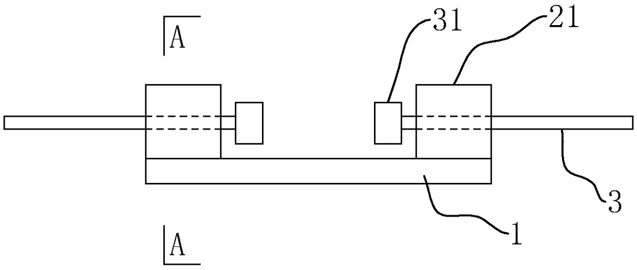
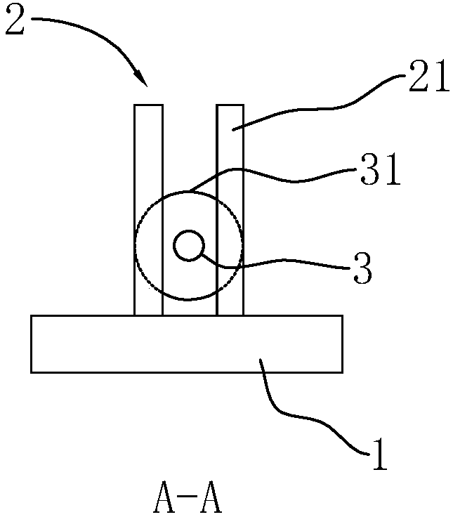
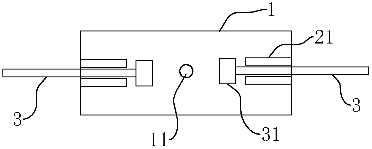
[0065] Such as figure 1 , figure 2 and image 3 As shown, a steel bar connection device and its connection structure, the connection device includes a bottom plate 1, two groups of U-shaped cards 2 vertically fixed on the upper surface of the bottom plate 1; two groups of U-shaped cards 2 are parallel to each other, and each group of U-shaped cards 2 includes two clamping pieces vertically fixed on the upper surface of the bottom plate 1; two connecting steel bars 3 to be connected are fixed with an expanding head 31 at one end close to the connecting device, and the gap between the two clamping pieces is larger than that to be connected. The outer diameter of connecting steel bar 3 is less than the size of enlarging head 31. The bottom plate 1 can be made of steel plate or strip steel, and the clamping part is a clamping plate 21 , and the direction of the clamping plate 21 is parallel to the direction of the connecting steel bar 3 .

[0066] Such as figure 1 As shown,...

Embodiment 2

[0070] The difference from Embodiment 1 is that: Figure 6 and Figure 7 As shown, the clamping plates 21 are arranged obliquely, and the two clamping plates 21 of each set of U-shaped cards 2 form a trumpet shape, and the opening of the horn faces the other set of U-shaped cards 2 . One end surface of the enlarging head 31 facing the pulling out of the connecting device is a circular table surface 32 . The horn opening is adapted to the round table surface 32 . Since the enlarged head 31 has a larger contact area with the clamping plate 21, the force is better.

Embodiment 3

[0072] The difference from Embodiment 1 is that: Figure 8 As shown, a pin hole is provided on the clamping plate 21 , and the clamping pin 4 penetrates into the pin hole to close the opening of the U-shaped clamp 2 . The clamping pin 4 closes the opening of the U-shaped clamp 2, which can prevent the connecting steel bar 3 from slipping out of the opening when subjected to a relatively large pulling force.


PUM


Abstract

The invention discloses a connecting device and a connecting structure of steel bars and a mounting method of the connecting structure. The connecting device and the connecting structure are characterized in that the connecting device of the steel bars comprises a bottom plate and two sets of U-shaped clamps perpendicularly and fixedly connected to the upper surface of the bottom plate; the two sets of U-shaped clamps are in parallel, and each set of U-shaped clamps comprises two clamping pieces which are perpendicularly and fixedly connected to the upper surface of the bottom plate; the connecting structure comprises the connecting device and two connecting steel bars, an amplifying head is fixedly connected to the end, close to the connecting device, of each connection steel bar, and thegap between every two clamping pieces is larger than the outer diameter of a to-be-connected steel bar and smaller than the size of each amplifying head; and the amplifying heads of the two connecting steel bars are opposite to each other and clamped into the two sets of U-shaped clamps. The connecting device of the steel bars is simple in structure, easy to machine and convenient to operate.

Description

technical field [0001] The invention relates to a steel bar connection device, in particular to a steel bar connection device, a connection structure and an installation method thereof. Background technique [0002] At present, the connection methods of prefabricated components in prefabricated concrete structure buildings, especially the vertical reinforcement connection methods of vertical components (prefabricated wall panels / columns) mainly include: 1) welding connection of embedded parts, 2) bolt connection of embedded parts , 3) There are three connection methods for steel sleeve grouting connection. [0003] 1) The welding connection of embedded parts is that the connecting steel plate is preset at the connecting part of the component, and after the prefabricated component is installed, the adjacent embedded steel plate between the components is welded and connected into one. [0004] Advantages: Simple installation and operation; Disadvantages: Due to the welding pr...

Claims


Application Information

Patent Timeline
Patent Type & Authority Applications(China)
IPC IPC(8): E04C5/16
CPCE04C5/163
Inventor 李藏柱
Owner 李藏柱
Why Eureka
Try Eureka