Super-resolution optical imaging method for forming small-hole probe based on double-beam transient trepanning

A pinhole probe and optical imaging technology, applied in the field of super-resolution optical imaging, can solve problems such as sample damage, and achieve the effects of low cost, remarkable imaging effect and simple operation

Active Publication Date: 2018-07-24
SHANGHAI INST OF OPTICS & FINE MECHANICS CHINESE ACAD OF SCI
View PDF2 Cites 4 Cited by
  • Summary
  • Abstract
  • Description
  • Claims
  • Application Information

AI Technical Summary

Problems solved by technology

However, too short a wavelength will cause damage to the sample, and the maximum numerical aperture of the system can only be close to 1.5

Method used


Image

  • Super-resolution optical imaging method for forming small-hole probe based on double-beam transient trepanning
  • Super-resolution optical imaging method for forming small-hole probe based on double-beam transient trepanning
  • Super-resolution optical imaging method for forming small-hole probe based on double-beam transient trepanning

Examples


Embodiment 1

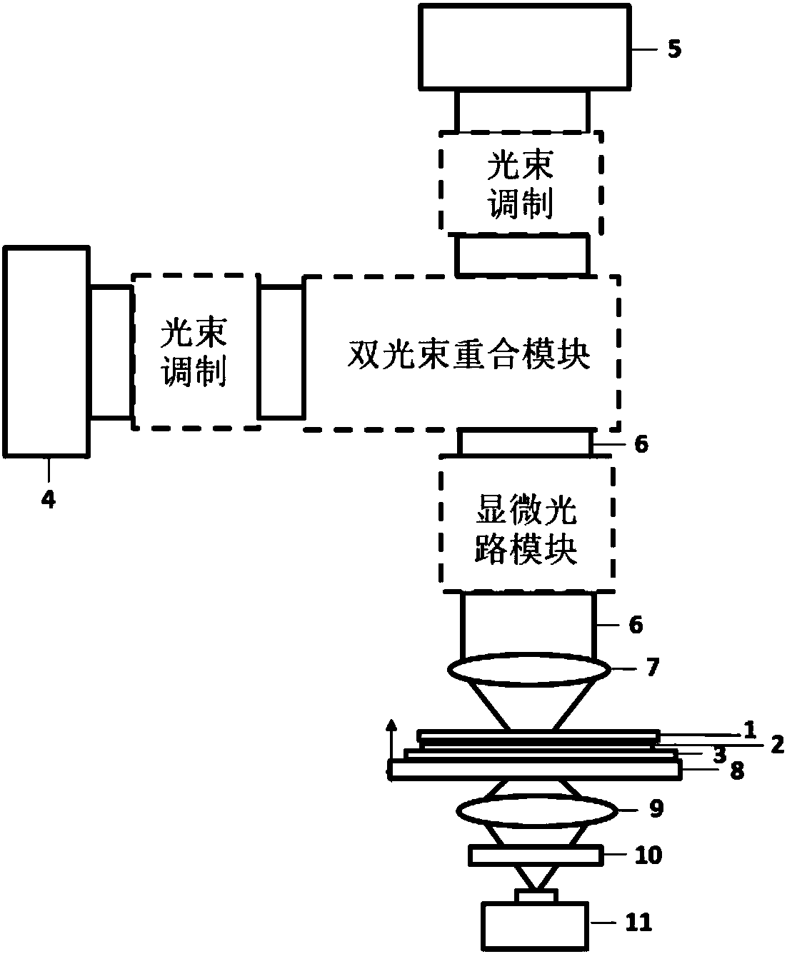
[0038] A super-resolution optical imaging method based on double-beam transient opening to form a pinhole probe, the steps of which include:

[0039] a) coating a layer of phase-change film material 2 on the cover glass 1 by magnetron sputtering;

[0040] b) The above-mentioned cover glass 1 coated with the phase-change thin film material 2 is closely attached to the surface of the sample 3 to be tested, and the side coated with the film is next to the sample;

[0041] c) placing the cover glass 1 and the sample 3 together on the imaging sample moving stage 8;

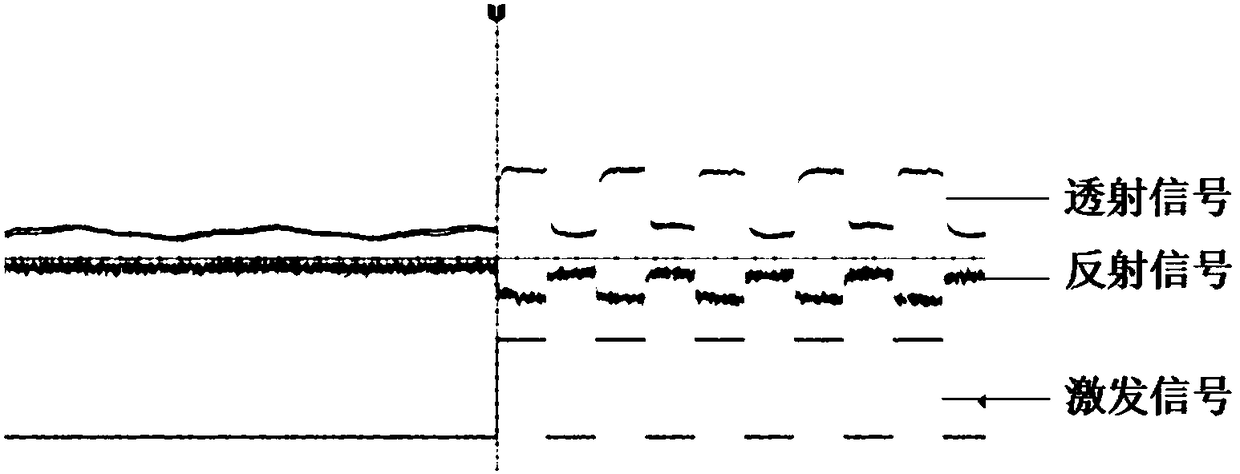
[0042] d) Using a beam of light with a power density less than 2×10⁹ W / m 2 The probe light 5 and a beam of light with the same wavelength have a power density greater than 2×10 9 W / m 2 , the excitation light 4 with a pulse frequency greater than 1Mhz passes through the cover glass 1 at the same time, and irradiates the same area on the sample 3;

[0043] e) pass the light signal transmitted through the cover glass ...

Embodiment 2

[0050] A super-resolution optical imaging method based on double-beam transient opening to form a pinhole probe, the steps of which include:

[0051] a) coating a layer of phase-change film material 2 on the cover glass 1 by magnetron sputtering;

[0052] b) The above-mentioned cover glass 1 coated with the phase-change thin film material 2 is closely attached to the surface of the sample 3 to be tested, and the side coated with the film is next to the sample;

[0053] c) placing the cover glass 1 and the sample 3 together on the imaging sample moving stage 8;

[0054] d) Using a beam of optical power density less than 2×10 9 W / m 2 The probe light 5 and a beam of light with the same wavelength have a power density greater than 2×10 9 W / m 2 , the excitation light 4 with a pulse frequency greater than 1Mhz irradiates the same area on the sample 3;

[0055] e) pass the light signal transmitted through the cover glass 1 and the sample 3 through a filter 10, and filter out the...


PUM

PropertyMeasurementUnit
thicknessaaaaaaaaaa

Abstract

The invention discloses a super-resolution optical imaging method for forming a small-hole probe based on double-beam transient trepanning. In a scanning microscope imaging system, the cover glass plated with a phase-change material thin film abuts against the surface of a sample, and then two beams focus the cover glass simultaneously to be irradiated onto the sample, one beam is high-power pulseexciting light, and the other beam is low-power probe light. By using the non-linear characteristic of the phase-change material, when the exciting light acts on the phase-change material, the material has a non-linear saturated absorption characteristic, transient small holes are formed in the material, the effective radius of the probe light decreases after the probe light passes through the transient small holes, and the small-hole probe lower than limit is formed; when the material has a non-linear anti-saturated characteristic, differentiation is carried out with a signal under a triggeraction by using a weak optical signal under an unexcited action, the transient small-hole probe lower than the limit can also be formed, point-by-point scanning imaging is realized by using the formed small-hole probe, and super-resolution far-field optical imaging is realized.

Description

technical field [0001] The invention relates to an optical imaging method, which is a super-resolution optical imaging method based on double-beam transient hole opening to form a pinhole probe. Background technique [0002] With the continuous development of society and the continuous advancement of science and technology, it has become an urgent need in various fields to realize nanoscale non-destructive imaging with optical methods. However, due to the limit of the optical system, the resolution cannot reach infinitely small, and there is an extreme value, which we call "optical diffraction limit". In 1873, the German scientist Abbe (Abbe) derived the diffraction resolution limit for the first time according to the diffraction theory, and later Rayleigh (Rayleigh) summarized Abbe's diffraction theory into a formula: [0003] [0004] Among them, r represents the minimum resolution distance, λ represents the laser wavelength, and NA represents the numerical aperture of...

Claims


Application Information

Patent Timeline
Patent Type & Authority Applications(China)
IPC IPC(8): G01N21/39G01N21/17
CPCG01N21/17G01N21/39G01N2021/1765G01N2021/178
Inventor 丁晨良魏劲松
Owner SHANGHAI INST OF OPTICS & FINE MECHANICS CHINESE ACAD OF SCI
Why Eureka
Try Eureka