A pre-combustion chamber ignition structure, system and working method thereof

A pre-combustion chamber and spark plug technology, applied in the field of pre-combustion chamber ignition structure, can solve the problems of reducing the total amount of mixture, high emissions, weak intensity of high-energy jets in the pre-combustion chamber, etc., so as to reduce the working cycle fluctuation rate, reduce HC and Effect of CO emission and shortening of flame propagation distance

Active Publication Date: 2019-10-15
SHANDONG UNIV
View PDF4 Cites 2 Cited by
  • Summary
  • Abstract
  • Description
  • Claims
  • Application Information

AI Technical Summary

Problems solved by technology

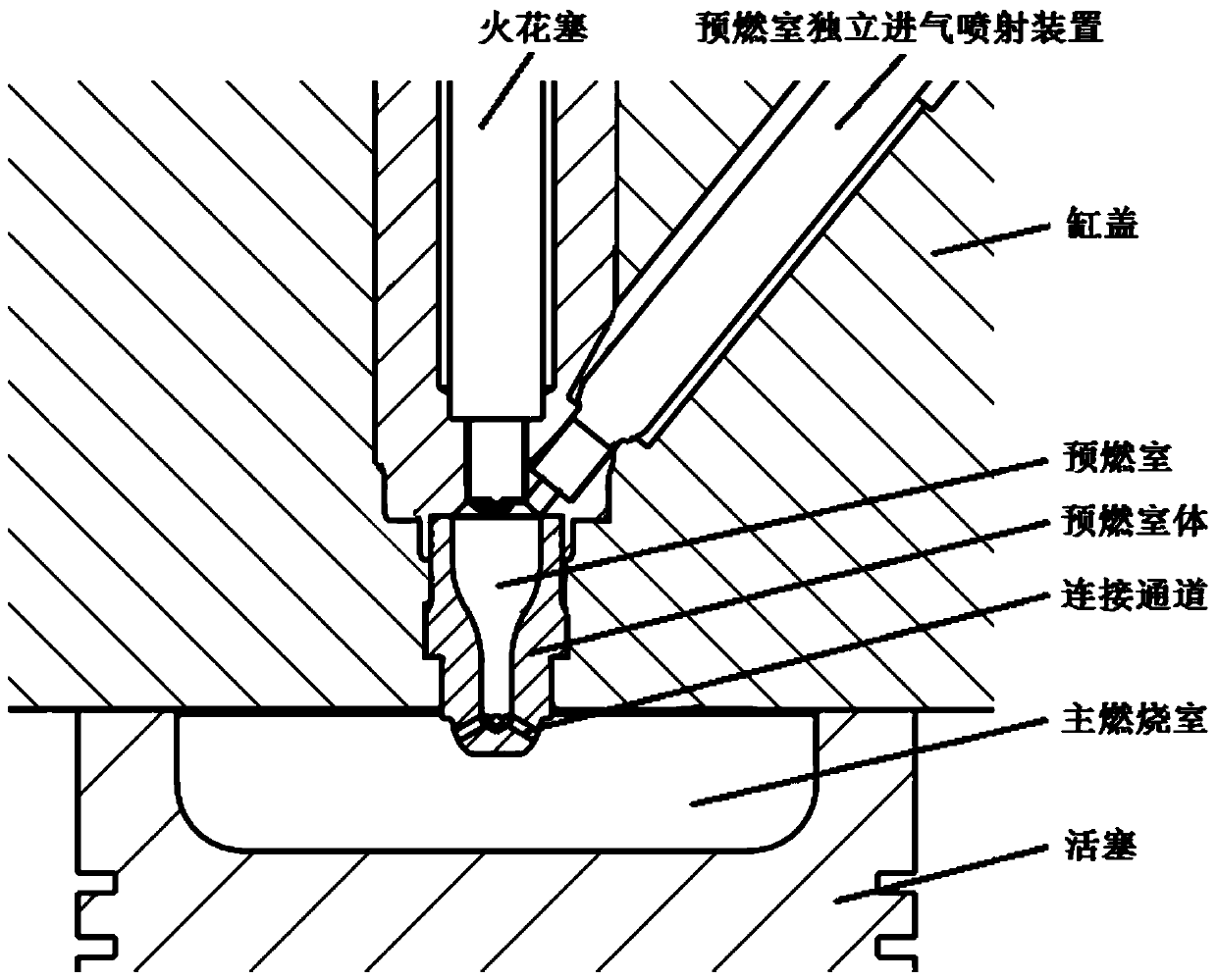
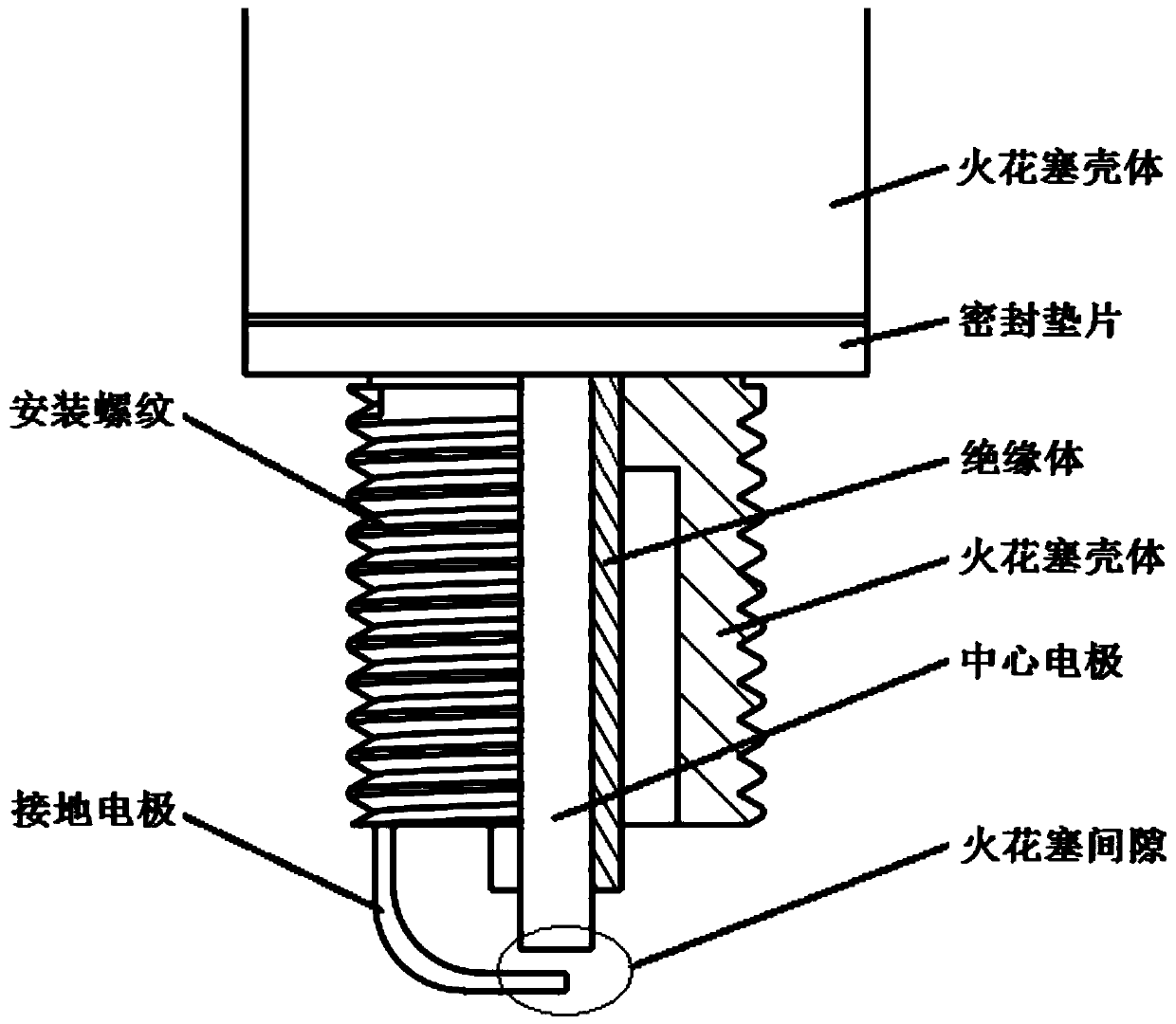
[0006] After the discharge and ignition between the spark plug center electrode and the ground electrode in the pre-combustion chamber ignition system, the flame core generated in the electrode gap gradually grows outward. When the temperature of the flame core rises to the ignition point of the natural gas mixture, it will ignite the mixture near the spark plug. Due to the low laminar flow velocity of the natural gas flame, the upper part of the pre-combustion chamber will first participate in the combustion, while the lower part of the mixed gas far away from the ignition position will pass through the connecting channel under the action of the upper combustion pressure in the pre-combustion chamber before the flame front arrives. After entering the main combustion chamber, the total amount of mixed gas participating in the combustion in the pre-combustion chamber is reduced, resulting in a lower peak combustion pressure in the pre-combustion chamber after ignition, and a smaller pressure difference between the pre-combustion chamber and the main combustion chamber, so that the The connecting channel between the pre-combustion chamber and the main combustion chamber enters the main combustion chamber. Burning speed in the combustion chamber, resulting in a longer duration of combustion in the main combustion chamber
[0007] After the two electrodes of the spark plug are discharged, the gas mixture near the gap of the spark plug is ignited, and the flame front develops outward from the center of the initial flame. The flow velocity is limited, and the mixed gas in the lower part of the pre-combustion chamber will enter the main combustion chamber through the connecting channel under the action of the upper combustion pressure in the pre-combustion chamber before the flame front arrives. Therefore, the jet composition of the pre-combustion chamber entering the main combustion chamber through the connecting channel in the early stage It is mainly unburned mixed gas, which has a low temperature and has no ignition effect on the lean mixed gas in the main combustion chamber; the late components of the jet in the pre-combustion chamber are mainly high-energy particles participating in combustion and high-temperature burned gas, and its temperature Higher than the ignition point of the natural gas mixture, it can ignite the lean mixture in the main combustion chamber, but because part of the mixture in the pre-combustion chamber is pressed into the main combustion chamber without participating in the combustion in the pre-combustion chamber, the amount of mixture gas participating in the combustion in the pre-combustion chamber is reduced , the intensity of the high-energy jet of the pre-chamber formed after combustion in the pre-chamber is relatively weak, and the flow velocity of the jet of the pre-chamber entering the main combustion chamber is relatively low, and the penetration distance of the jet is relatively short. The distributed ignition coverage area formed indoors is small
Limited by the composition and strength of the jet in the pre-chamber, it is difficult for the existing pre-chamber ignition system to give full play to the energy released after the combustion of the mixture in the pre-chamber, resulting in low ignition reliability of the lean mixture in the main combustion chamber, and frequent fluctuations in the engine working cycle. Big
[0008] In summary, the position of the spark plug and spark plug gap used in the current pre-chamber ignition system makes the flame propagation distance in the pre-chamber longer, resulting in part of the mixed gas in the pre-chamber not participating in the combustion in the pre-chamber and burning in the upper part of the pre-chamber. Under the action, the pre-chamber is discharged through the connecting channel, which reduces the amount of mixed gas participating in the combustion in the pre-chamber, and reduces the jet energy of the pre-chamber formed after combustion in the pre-chamber, which has an ignition effect on the lean mixture in the main combustion chamber, so that the pre-chamber The distributed ignition coverage area formed by the combustion chamber jet in the main combustion chamber is small, which reduces the ignition reliability of the lean mixture in the main combustion chamber. The combustion duration of the lean mixture in the main combustion chamber is longer, and the engine combustion cycle fluctuates greatly, so The unburned HC and CO emissions in the exhaust are high, and the potential ignition energy of the pre-chamber is difficult to be effectively utilized

Method used


Image

  • A pre-combustion chamber ignition structure, system and working method thereof
  • A pre-combustion chamber ignition structure, system and working method thereof
  • A pre-combustion chamber ignition structure, system and working method thereof

Examples


example

[0041] AVL FIRE is a professional engine performance simulation software, which can accurately simulate the flow and combustion process in the engine cylinder. Using AVL FIRE software, the simulation comparison analysis was carried out on the traditional pre-combustion chamber ignition structure (case1) with the spark plug gap placed on the top of the pre-combustion chamber and the pre-combustion chamber ignition structure (case2) with the spark plug gap moved down in the patent of the present invention. Figure 5(a)-Figure 5(c) and Figure 6(a)-Figure 6(c) It is the cloud map of the flame surface density in the pre-combustion chamber after ignition, which characterizes the flame propagation process in the pre-combustion chamber after the two pre-chamber structures are ignited. In case1, such as Figure 5(a)-Figure 5(c) As shown, after the upper part of the pre-chamber is ignited, the flame first spreads on the top of the pre-chamber, and then spreads downward. Under the act...


PUM


Abstract

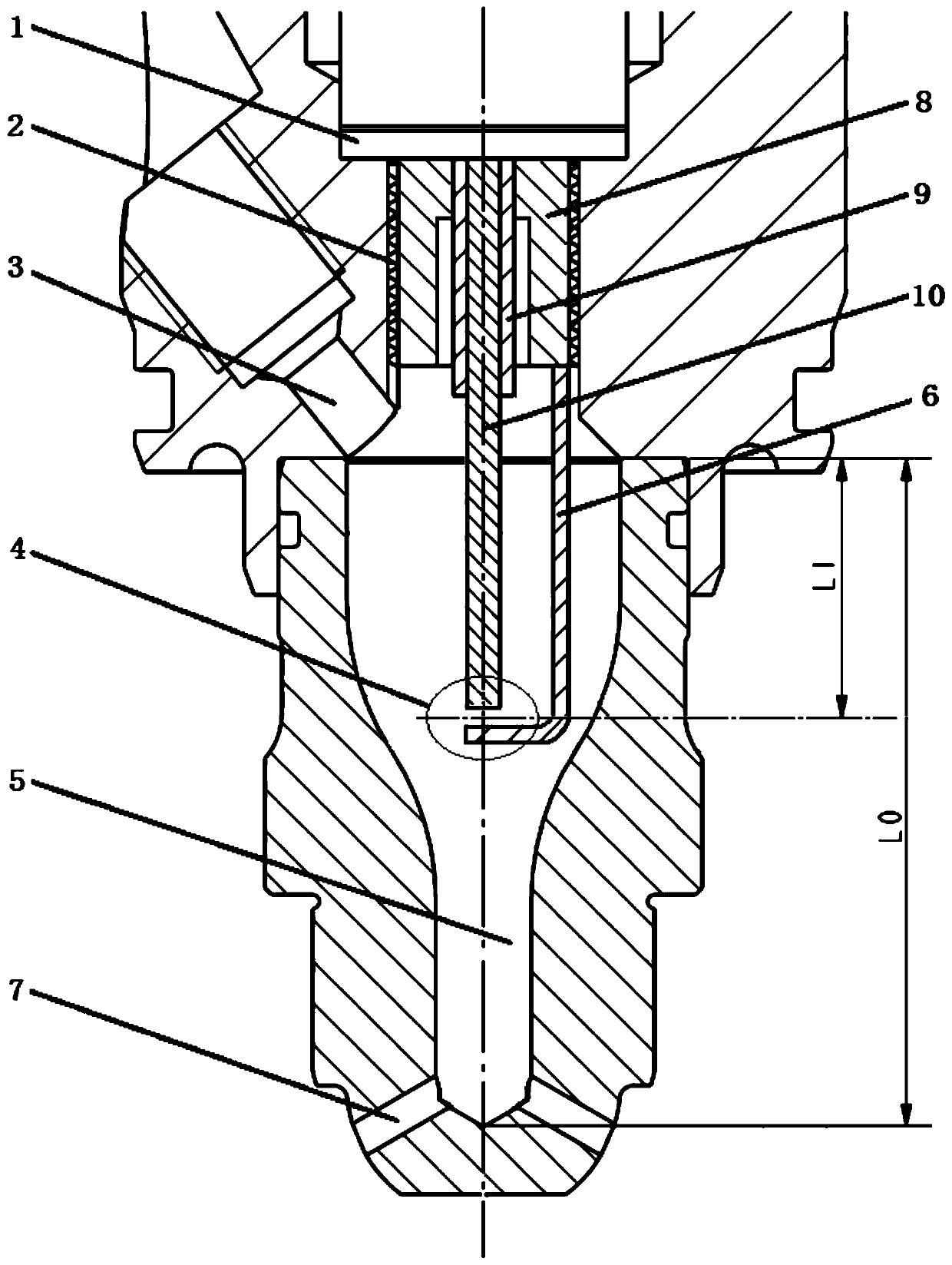
The invention discloses a pre-combustion chamber ignition structure, a pre-combustion chamber ignition system and a working method thereof. The pre-combustion chamber ignition structure comprises a central electrode extending into a pre-combustion chamber; a grounding electrode is disposed to an end portion of the central electrode; and a spark plug clearance located inside the pre-combustion chamber is formed between the central electrode and the grounding electrode. According to the pre-combustion chamber ignition structure, pre-combustion chamber ignition system and working method thereof of the invention, more mixed gases participate in combustion in the pre-combustion chamber; jet flow components entering a main combustion chamber through the connection passage of the pre-combustion chamber after the spark plug performs ignition can be significantly improved; energy carried by the jet flow of the pre-combustion chamber can be increased; a distributed ignition coverage area formedafter the jet flow of the pre-combustion chamber enters the main combustion chamber can be increased; the ignition energy of the ignition system of the pre-combustion chamber can be significantly improved; and the reliable ignition of a lean mixture in the main combustion chamber can be ensured; the propagation distance of flames in the main combustion chamber can be shortened; the lasting duration of combustion in the main combustion chamber can be shortened; combustion heat efficiency can be improved; the cyclical fluctuation ratio of the operation of an engine can be reduced; the operational stability of the engine can be significantly improved; and HC and CO emissions can be reduced.

Description

technical field [0001] The invention relates to the technical field of internal combustion engines, in particular to a pre-combustion chamber ignition structure, system and working method thereof. Background technique [0002] Large-bore natural gas engines are more and more widely used in inland ship power, oil drilling power, gas generator sets and other fields. In order to improve their economy and thermal efficiency and reduce nitrogen oxide emissions, lean combustion is mostly organized in the cylinder. However, in practical applications, due to the slow propagation speed of natural gas-air flames and the long distance of flame propagation in the combustion chamber of large-bore natural gas engines, when the tissue in the cylinder is leanly burned, the combustion duration of the engine is longer, the cycle changes greatly, and the emissions of unburned HC and CO are high. . The use of the pre-combustion chamber ignition system can significantly enhance the ignition ene...

Claims


Application Information

Patent Timeline
Patent Type & Authority Patents(China)
IPC IPC(8): H01T13/32F02B19/14F02B19/16F02B9/04
CPCF02B9/04F02B19/14F02B19/16H01T13/32Y02T10/12
Inventor 程勇杨雪王玉宝
Owner SHANDONG UNIV
Why Eureka
Try Eureka